
1.16 Time System Service Multi Client
This example application demonstrates the multi-client system timer functionality.
Description
- This application demonstrates timer functionality (with two clients to the Time System Service) by periodically printing a message on console every two seconds and blinking an LED every one second
- Delay, counter and single shot timer functionality is demonstrated on a switch press
- On a switch press, the application reads the current value of the 64-bit counter (say, count 1)
- It then starts a delay of 500 ms and waits for the delay to expire
- Once the delay has expired, the application again reads the current value of the 64-bit counter (say, count 2) and calculates the difference between the two counter values
- The difference count indicates the time spent for the delay and is printed on the console as, Delay time = x ms, where x is the delay value and is equal to 500 ms in the given example
- The application then starts a single shot timer of 100 ms
- When the single shot timer
expires, a message is printed on the console that says
Single shot timer of 100 ms expired - This message is printed only once on every switch press
Downloading and Building the Application
To clone or download this application from GitHub, go to the main page of this repository and then click Clone button to clone this repository or download as zip file. This content can also be downloaded using content manager by following these instructions.
Path of the application within the repository is apps/system/time/sys_time_multiclient/firmware.
To build the application, refer to the following table and open the project using its IDE.
| Project Name | Description |
|---|---|
| pic32mk_gp_db.X | MPLAB X project for PIC32MK GP Development Kit |
| pic32mk_mcj_curiosity_pro.X | MPLAB X project for PIC32MK MCJ Curiosity Pro Development Board |
| pic32mk_mcm_curiosity_pro.X | MPLAB X project for PIC32MK MCM Curiosity Pro Development Board |
| pic32mk_mca_curiosity_pro.X | MPLAB X project for PIC32MK MCA Curiosity Pro Development Board |
Setting Up the Hardware
The following table shows the target hardware for the application projects.
| Project Name | Description |
|---|---|
| pic32mk_gp_db.X | PIC32MK GP Development Kit |
| pic32mk_mcj_curiosity_pro.X | PIC32MK MCJ Curiosity Pro Development Board |
| pic32mk_mcm_curiosity_pro.X | PIC32MK MCM Curiosity Pro Development Board |
| pic32mk_mca_curiosity_pro.X | PIC32MK MCA Curiosity Pro Development Board |
Setting Up PIC32MK GP Development Kit
- Connect micro USB cable to the Debug USB connector (J12) on the board to the computer
- Connect a micro USB cable to the USART-USB port J25. This will enumerate as a COM port on the PC.
Setting Up PIC32MK MCJ Curiosity Pro Development Board
- Connect micro USB cable to the Debug USB connector (J1) on the board to the computer. This will enumerate as a COM port on the PC.
Setting Up PIC32MK MCM Curiosity Pro Development Board
- Connect a micro USB cable to the USB DEBUG port J500
- Connect a micro USB cable to the USB to UART port J400. This will enumerate as a COM port on the PC.
Setting Up PIC32MK MCA Curiosity Pro Development Board
- Connect micro USB cable to the Debug USB connector (J1) on the board to the computer. This will enumerate as a COM port on the PC.
Running the Application
- Open the Terminal application (e.g., Tera Term) on the computer.
- Connect to the EDBG Virtual COM port and configure the serial settings as
follows:
- Baud: 115200
- Data: 8 Bits
- Parity: None
- Stop: 1 Bit
- Flow Control: None
- Build and program the application using its IDE.
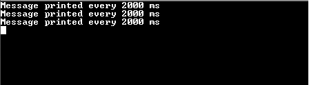
- Observe the following message
getting printed on the console every two seconds.
- Press the switch and observe the
following output on the terminal (highlighted in red box).
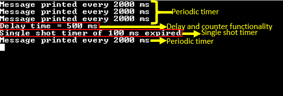
Delay time = 500
                                ms
indicates the amount of time spent during the delaySingle shot timer of 100 ms expiredis printed only once on every switch press
- LED indicates the periodic timer
functionality:
- LED is toggled periodically every one second
Refer to the following table for Switch and LED names:
| Board | Switch Name | LED Name |
|---|---|---|
| PIC32MK GP Development Kit | S1 | LED1 |
| PIC32MK MCJ Curiosity Pro Development Board | SW200 | LED2 |
| PIC32MK MCM Curiosity Pro Development Board | SW1 | LED2 |
| PIC32MK MCA Curiosity Pro Development Board | SW200 | LED1 |