5 Implementation
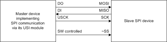
This application note describes the implementation of an SPI driver for both master and slave communication. An example setup with the USI module as an SPI master is shown in the figure below. The driver is written as a standalone driver that easily can be included into the main application. Use the code as an example, or customize it for own use. All relevant functions and global variables are prefixed with ‘spiX_’, so a quick search-and-replace is enough to rename the driver interface in case of naming conflicts.
The driver uses the USI module and the USI counter overflow interrupt. Therefore, interrupts must be enabled to be able to use the driver. In master mode the driver also uses Timer/Counter0. The T/C0 compare match interrupt is used to generate the master clock signal.
The driver interface consists of these functions:
- spiX_initmaster, which initializes the driver in master mode
- spiX_initslave, which initializes the driver in slave mode
- spiX_put, which starts a transfer in master mode, or prepares a byte in slave mode
- spiX_get, which returns the last incoming byte
- spiX_wait, which waits for a transfer to finish
Note that the Slave Select (SS) line of the SPI bus must be controlled manually in software if required by the slave device. When using the USI as an SPI slave, you also need to watch the incoming SS line with, for instance, an interrupt line if required. The driver in this application note does not use the SS line.
The following global variables are also available:
- spiX_status, which contains the driver status flags
- storedUSIDR, which contains the last incoming byte. This should be accessed with the spiX_get() function only.
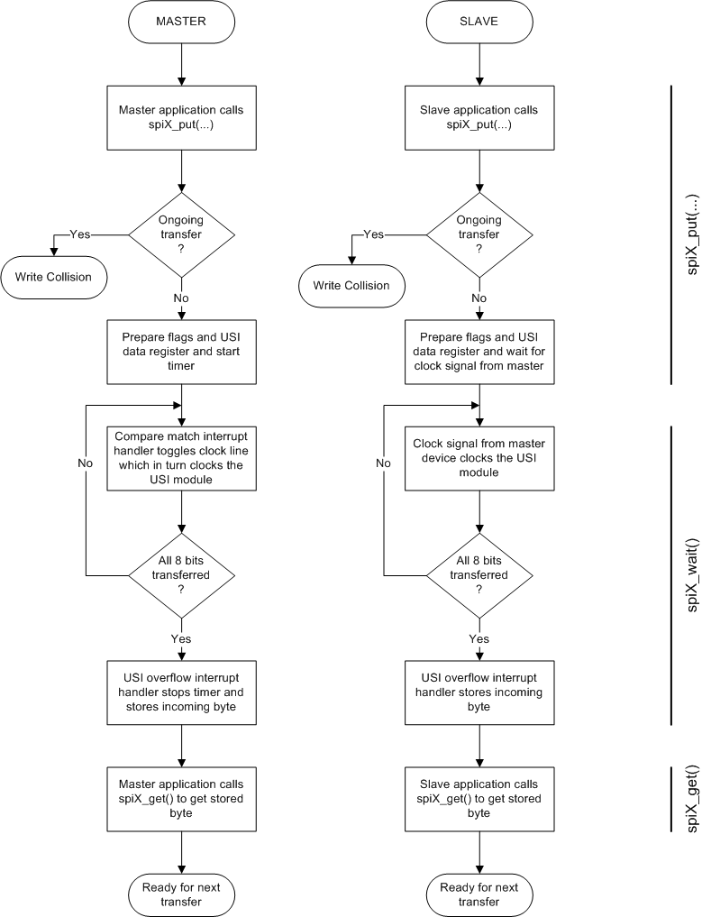
The functions are documented in the source code. In addition, the simplified flowchart for a typical byte transfer session is given in the figure below. The example source code accompanying this application note shows an implementation of such a session.
Note that the part of the flowchart below grouped under the spiX_wait() function is performed by interrupt handlers and not the function itself. The function just waits for the transfer complete flag to be set.
The example code is written for Atmel START. It can be downloaded from "BROWSE EXAMPLES" entry of Atmel START for both Atmel Studio 7 and IAR IDE. Double click the downloaded .atzip file and the project will be imported to Atmel Studio 7. To import the project in IAR, refer "Atmel START in IAR" , select Atmel Start Output in External Tools -> IAR.