
1.6.4 PIC32WM BZ6 Curiosity Evaluation Board: Building and Running the File System Based QSPI Flash Bootloader Applications
Downloading and Building the Application
To clone or download this application from GitHub, go to the main page of this repository and then click Clone button to clone this repo or download as zip file. This content can also be download using content manager by following these instructions.
Path of the application within the repository is apps/fs/qspi/.
To build the application, refer to the following table and open the project using its IDE.
Bootloader Application
| Project Name | Description |
|---|---|
| bootloader/firmware/pic32wm_bz6_curiosity.X | MPLAB X Project for PIC32WM BZ6 Curiosity Evaluation Board |
Programmer Application
| Project Name | Description |
|---|---|
| app_programmer/firmware/pic32wm_bz6_curiosity.X | MPLAB X Project for PIC32WM BZ6 Curiosity Evaluation Board |
Setting Up PIC32WM BZ6 Curiosity Evaluation Board
- To run the demo, the following
additional hardware are required:
- One microSD click
- One micro SD Card
- Install the microSD click on to the mikroBUS 1 of the device
- Connect the Debug USB port on the board to the computer using a micro USB cable
Running the Application
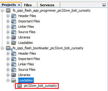
- Open the bootloader project bootloader/firmware/pic32wm_bz6_curiosity.X in the IDE.
- Ensure that the
app_programmer/firmware/pic32wm_bz6_curiosity.X is added as a
loadable project to bootloader application.
- As the QSPI Flash memory may not have any valid binary required by bootloader for the first time. Adding the app_programmer as loadable allows MPLAB X to create a unified hex file and program both these applications in their respective memory locations based on their linker script configurations.
- Open the Terminal application (e.g., Tera Term) on the computer to get programmer application messages through UART once loaded.
- Configure the serial port
settings as follows:
- Baud: 115200
- Data: 8 Bits
- Parity: None
- Stop: 1 Bit
- Flow Control: None
- Build and program the bootloader application using the IDE.
- Once programming is done,
bootloader starts execution and directly jumps to application space to run the
programmer application.
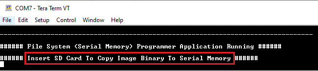
- RGB_LED_RED starts
blinking indicating that the programmer application is running and the
user should see below output on the console
- RGB_LED_RED starts
blinking indicating that the programmer application is running and the
user should see below output on the console
- Open the programmer application project app_programmer/firmware/pic32wm_bz6_curiosity.X in the IDE.
- Update
app_programmer/firmware/src/app_monitor.c to update printf message
from Serial Memory to QSPI Flash Memory as
below.
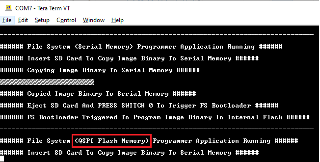
printf("\r\n###### File System (QSPI Flash Memory) Programmer Application Running ######\r\n"); - Clean and Build the project to generate the binary (Do not program the binary).
- Copy the generated application
binary file to a sdcard from the Host
PC.
<harmony3_path>/bootloader_apps_serial_memory/apps/fs/qspi/app_programmer/
pic32wm_bz6_curiosity.X/dist/pic32wm_bz6_curiosity/production/
pic32wm_bz6_curiosity.X.production.bin
- Rename the copied application binary file to image.bin.
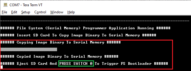
- Insert the sdcard with the application binary image.bin in the sdcard slot of the device.
- Following figure shows output of
successfully copying the programmer application binary to QSPI Flash Memory.
- RGB_LED_RED should still
be blinking
- RGB_LED_RED should still
be blinking
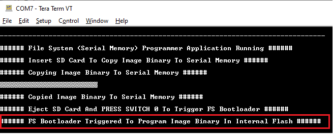
- Remove the sdcard from the sdcard slot.
- Press and hold the Switch
USR_BTN_1 to trigger Bootloader from programmer application, then press
NMCLR button twice and the user should see below output.
- Once Firmware Update is
successful, RGB_LED_RED should start blinking indicating updated programmer
application running and the user should see below output on the console.
Additional Steps (Optional)
- To bootload any other application
refer to the Application
ConfigurationsNote: This application should have programming capabilities to QSPI Flash Memory.
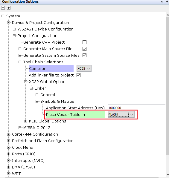
- Application vector table need to be placed in the FLASH memory (from
BOOT_FLASH to FLASH memory)
- Application vector table need to be placed in the FLASH memory (from
BOOT_FLASH to FLASH memory)
- Once done, repeat the applicable steps mentioned in Running the Application