Jump to main content
4.1 MCC Configuration
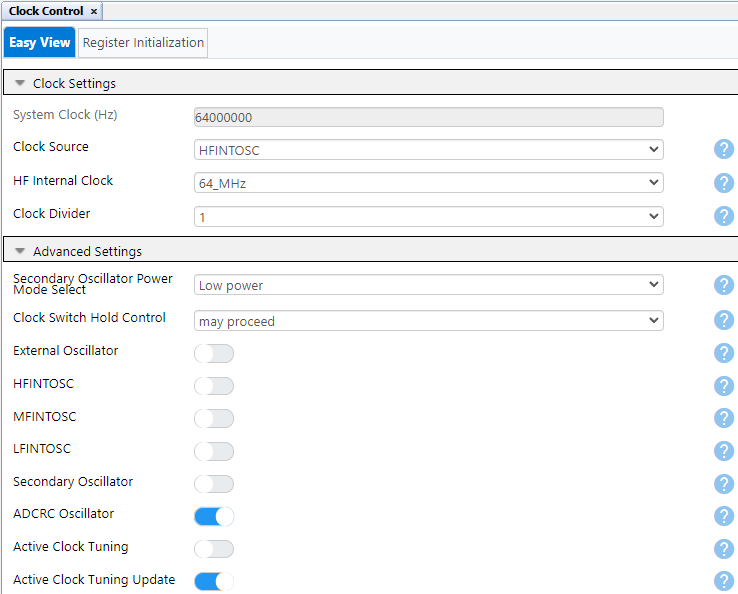
Clock Control configuration:
Clock Source: HFINTOSC
HF Internal Clock: 64
MHz
ADCRC Oscillator:
Enabled
Figure 4-1. MCC Clock Control
Configuration
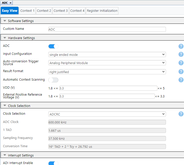
ADC configuration:
Input Configuration:
Single-Ended mode
Auto-conversion Trigger
Source: Analog Peripheral Module
Result Format: Right
justified
VDD : 3.3V
Clock Selection: ADCRC
Figure 4-2. MCC ADC Easy View
Configuration
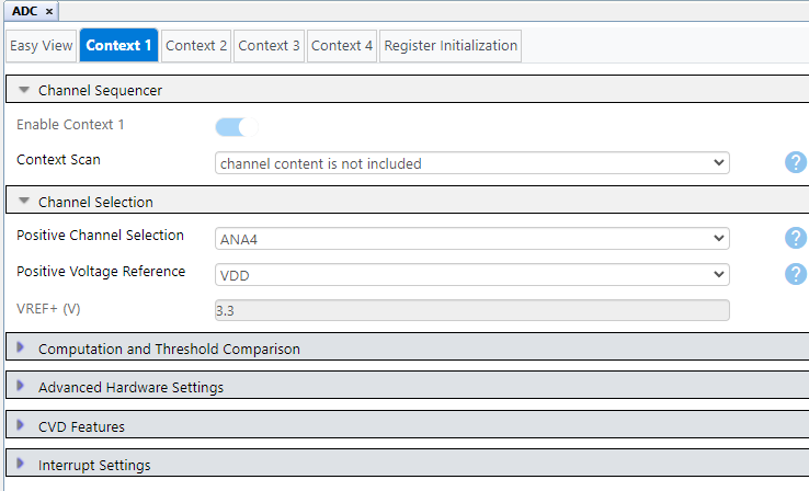
ADC Context 1 tab:
Positive Channel Selection:
ANA4
Positive Voltage Reference:
VDD
Operating Mode Selection:
Basic mode
Figure 4-3. MCC ADC Context 1
Configuration
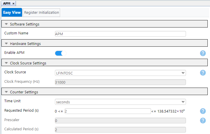
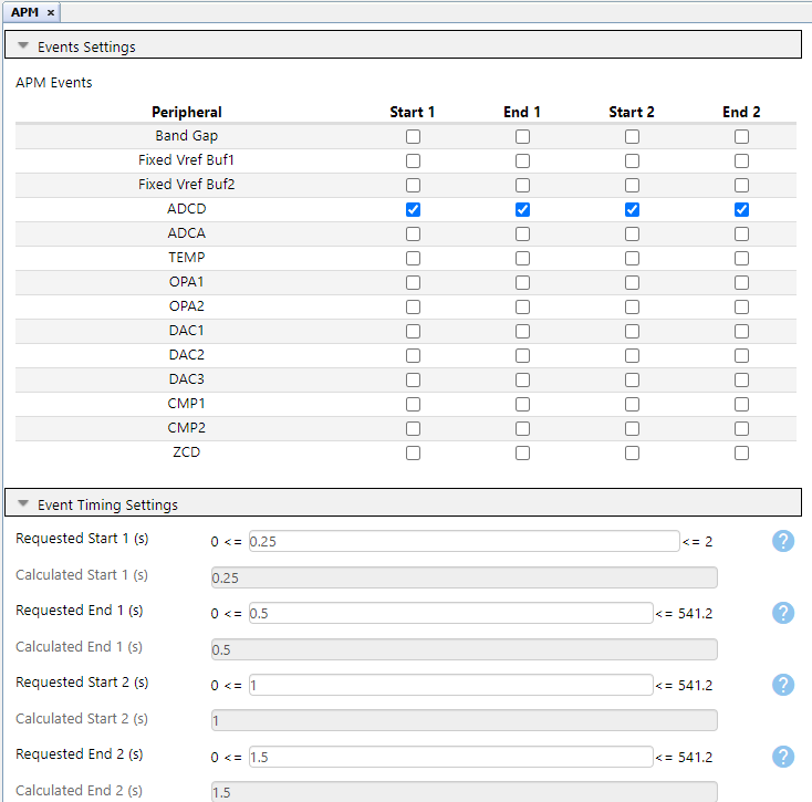
APM configuration:
Clock Source: LFINTOSC
Requested Period: 2s
APM Events: Start1 → ADCD,
End1 → ADCD, Start2 → ADCD, END2 → ADCD
Requested Start1: 0.25s
Requested End1: 0.5s
Requested Start2: 1s
Requested End2: 1.5s
APM: Enabled
Figure 4-4. MCC APM Configuration – 1 Figure 4-5. MCC APM Configuration – 2
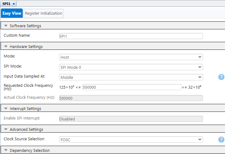
SPI1 configuration:
Operation Mode: Host
SPI Mode: SPI Mode 0
Input Data Sampled At:
Middle
Requested Clock Frequency 500
kHz
Clock Source Selection:
FOSC
Figure 4-6. MCC SPI Configuration
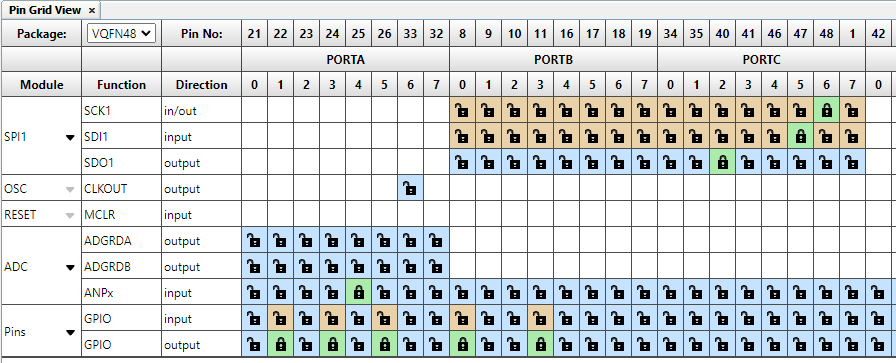
Figure 4-7. MCC Pins Configuration – 1
Figure 4-8. MCC Pins Configuration – 2
The online versions of the documents are provided as a courtesy. Verify all content and data in the device’s PDF documentation found on the device product page.