Jump to main content
2.1 MCC Configuration
Clock Control configuration:
Clock Source: HFINTOSC
HF Internal Clock: 64
MHz
ADCRC Oscillator:
Enabled
Figure 2-1. MCC Clock Control Configuration
ADC configuration:
Input Configuration:
Differential mode
Result Format: Right
justified, two’s complement
VDD : 3.3V
Clock Selection: ADCRC
Figure 2-2. MCC ADC Easy View Configuration
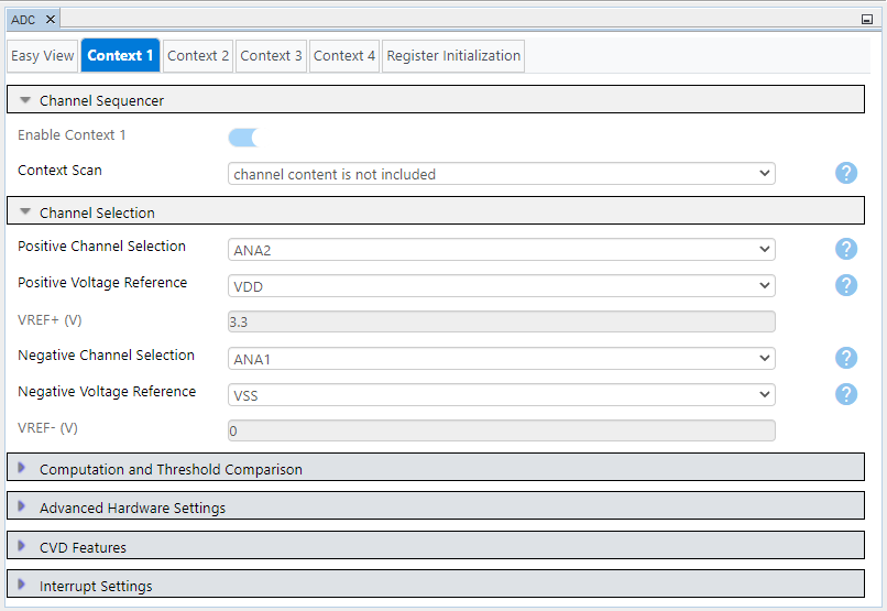
ADC Context 1 tab:
Positive Channel Selection:
ANA2
Positive Voltage Reference:
VDD
Negative Channel Selection:
ANA1
Negative Voltage Reference:
VSS
Operating Mode Selection:
Basic mode
Double Sampling
Figure 2-3. MCC ADC Context 1 Configuration
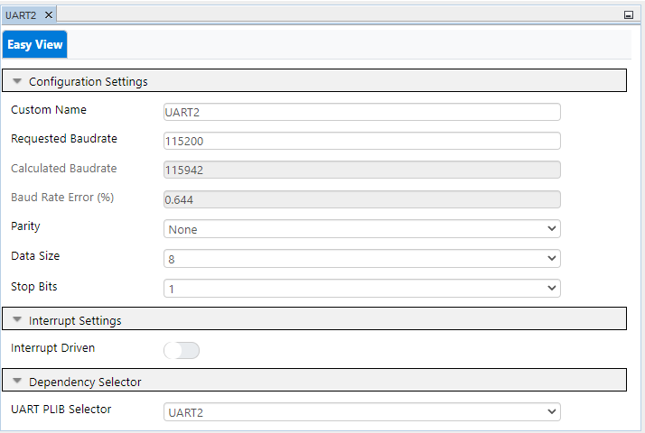
UART2:
115200 baud rate
Eight data bits
No parity bit
One stop bit
Figure 2-4. MCC UART Configuration
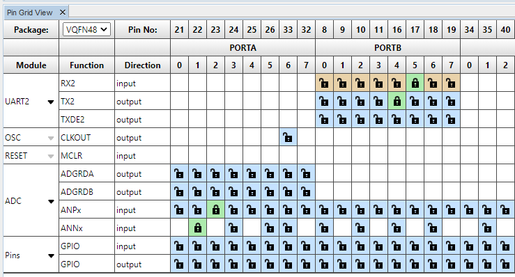
Figure 2-5. MCC Pins Configuration
The online versions of the documents are provided as a courtesy. Verify all content and data in the device’s PDF documentation found on the device product page.