3.2 Connecting and Communicating with Wireless Kit
Depending on the ports that are provided in the target HW or Kit, the communication between the PC and the kit can be established in the following ways:
-
Using the Embedded Debugger USB port
Some of the Atmel kits (e.g., ATmega256RFR2 Xplained Pro and SAM R21 Xplained Pro) has an in-built Embedded Debugger (EDBG) that is connected to the UART port of the Target MCU. When the PC is connected to the Debug/EDBG USB port, the connection is enumerated as a virtual COM port. The Performance Analyzer application firmware for the boards with EDBG are designed to communicate to PC using this virtual COM port.
Transceivers like RF215 support dual band operation. The Performance Analyzer tool for such devices uses two Virtual COM ports for communication to target HW:-
Virtual COM port that represents the Debug USB port (MCU's UART connected to EDBG) to configure the Sub-Gigahertz band
-
Virtual COM port that represents the Target USB port (USB port of the target MCU) to configure 2.4GHz band. (The USB-CDC firmware driver configures/controls this USB port.)
Refer to the following sections for connecting to kits that support dual-band operation like RF215.
-
-
Using the UART/COM port in the target HW board
If the kit or Target HW has only UART port(s), then the Performance Analyzer application firmware would be designed to use the UART port for communication with PC. Connect the UART port to PC's COM port. The USB to UART serial interface adapters can be used to connect the USB port on the PC to communicate with the UART port on the target hardware.
If the target HW uses transceivers like RF215, two UART ports (if USB ports are not available) needs to be supported to access the two bands.
Refer to the application note for details about how to connect Atmel wireless kits to the computer.
Connect the wireless kit to the PC as explained above. Open the Performance Analyzer using the 'Performance Analyzer' toolbar button or menu item under 'Tools' menu and follow these steps:
-
Using the “Select port to connect” drop-down list, select the port to which the wireless kit has been connected.

For RF215, two COM ports needs to appear in this drop down list, each representing a band - Sub-GHz and 2.4GHz.
-
Click on the button “Connect”.
-
A COM Settings window will pop up as shown below. The following image shows the recommended and default COM port settings for Atmel kits. However, the firmware could be changed in order to use a different COM port setting.
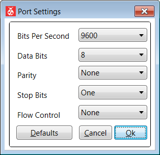
Click on the Ok button to establish communication with the wireless kit.
Clicking on the button Default will reset all selections to default values.
-
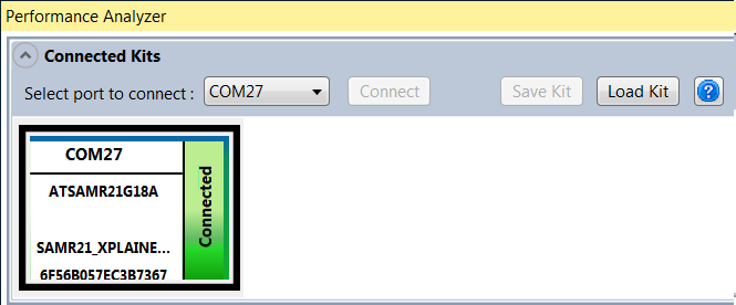
If the communication to the wireless kit has been established successfully, the wireless kit module will appear on the “Connected Kits” view in the Performance Analyzer application as shown below. The status of the kit is shown as “Connected”.
 Note:
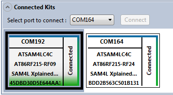
Note:If the connected kit is RF215 (that supports dual-band operation), then the Sub-GHz and 2.4GHz configurations needs to be connected using two COM ports. The following image shows how these two bands/configurations will appear in Performance Analyzer UI:
-
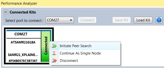
From here, right click to select either Paired mode or Single mode operation.
-
Refer to the following sections to start the Performance Test Applications.
-
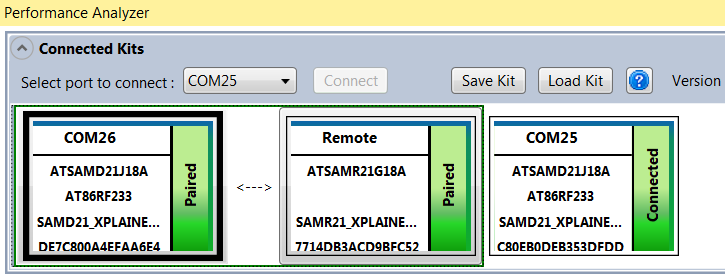
Multiple wireless kits can be connected to the Performance Analyzer. In this case, multiple kit modules will be shown in the “Connected Kits” view. When one of the kits is selected, the Performance Analyzer window updates its contents/context depending on the state of the selected kit.
-
To disconnect the kit, right click on the wireless kit to invoke a pop-up menu. Click on the menu “Disconnect” to disconnect the kit.
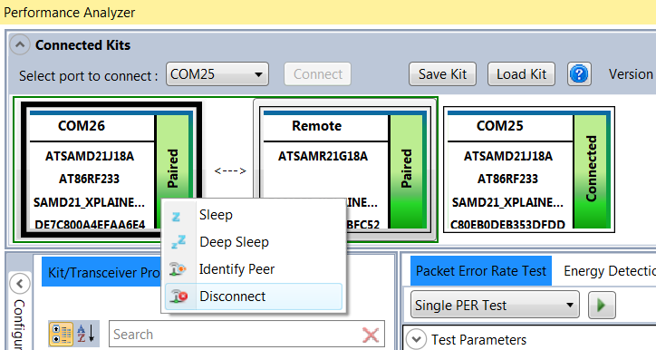
After disconnecting a wireless kit, in order to use it again, the kit should be disconnected, reset, and reconnected to the computer.
