
3.3.4 WiFi based RGB LED Control Application on Curiosity PIC32MZ EF 2.0 Development Board
Description
The WiFi RGB Easy Configuration demo showcases how to configure an embedded WiFi device that does not have a natural keyboard and screen. By using the internal Web server that accompanies the Microchip TCP/IP stack, end-users can use their browser to control the RGB(RedGreenBlue) LED.
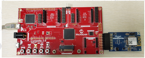
The Curiosity PIC32MZ EF 2.0 Development Board provides an XPRO connector. The XPRO connector is plugged with the ATWINC1500-XPRO board to configure WiFi connectivity. The demo features changing the color of the on-board RGB LED using the webpage hosted by the Curiosity board.
Modules/Technology Used
- Peripheral Modules
- Output compare
- Core Timer
- NVM
- Driver Modules
- Memory Driver
- Middleware Libraries
- TCP/IP Stack
- System Service Libraries
- File System
- SYS Console
- SYS Command
- STDIO Library
- WINC1500 Driver
Hardware Used
Software/Tools Used
This project has been verified to work with the following versions of software tools:
Refer Project Manifest present in harmony-manifest-success.yml under the project folder firmware/src/config/default.
- Refer the Release Notes to know the MPLAB X IDE and MCC Plugin version.
Because Microchip regularly updates tools, occasionally issue(s) could be discovered while using the newer versions of the tools. If the project does not seem to work and version incompatibility is suspected. It is recommended to double-check and use the same versions that the project was tested with. To download original version of MPLAB Harmony v3 packages, refer to document How to Use the MPLAB Harmony v3 Project Manifest Feature (DS90003305).
Setup
- Connect ATWINC1500-XPRO to Extension header (J501) on Curiosity PIC32MZ EF 2.0 Development Board.
- Power the Curiosity PIC32MZ EF 2.0
Development Board from a Host PC through a Type-A male to micro-B USB cable connected
to Micro-B port (J700).
Programming hex file
The pre-built hex file can be programmed by following the below steps.
- Open MPLAB X IDE
- Close all existing projects in IDE, if any project is opened.
- Go to File -> Import -> Hex/ELF File.
- In the Import Image File window,
- Create Prebuilt Project,
- Click the Browse button to select the prebuilt hex file.
- Select Device as PIC32MZ2048EFM14.
- Ensure the proper tool is selected under Hardware Tool and click on Next button.
- Select Project Name and Folder,
- Select appropriate project name and folder and click on Finish button
- Create Prebuilt Project,
- In MPLAB X IDE, click on Make and Program Device button to program the device.
- Follow the steps in Running the Demo section below.
- Open the project (wifi_rgb_easy_configuration\firmware\pic32mz_ef_curiosity_v2.X) in MPLAB X IDE.
- Ensure Curiosity/Starter Kits PKOB4 is selected as hardware tool to program/debug the application.
- Navigate to ../reference_apps/apps/pic32mz_ef_curiosity_v2/wifi_rgb_easy_configuration/firmware/src/utilities folder
- Double click on mpfs2 jar file.Note: Make sure java is installed.
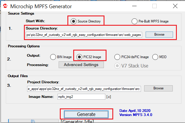
- Select Source Directory and browse to the folder ../reference_apps/apps/pic32mz_ef_curiosity_v2/wifi_rgb_easy_configuration/firmware/src/web_pages as shown in below image.
- Select PIC32 Image and click on
Generate button to generate mpfs_img2.c file as shown in below image.
- Build the code and program the device by clicking on the Make and Program button in MPLAB X IDE tool bar.
- Follow the steps in Running the Demo section below.
Running the Demo
- Open Tera Term, connect to serial console. If there is any connection issue on Tera terminal, unplug the USB cable connected to Micro-B port, and reconnect it back.
- Change the baud rate to 115200.
- Perform a reset by pressing the "RESET" switch.
- The serial terminal displays the
below
message.
"TCP/IP Stack: Initialization Started TCP/IP Stack: Initialization Ended - success SYS_Initialize: The MPFS2 File System is mounted WINC IP Address: 192.168.1.1" - When the demonstration runs, the WINC1500 goes into SoftAP mode (it behaves as an access point) and displays itself as MCHPSoftAP network.
- From a smartphone or personal computer, connect to the "MCHPSoftAP" network, which is the SoftAP network started by the demonstration. Then, bring up a web page by entering the IP address(e.g., 192.168.1.1) of the SoftAP network into the smartphone browser.
- When the web page is displayed, On the right top corner of the page, there is a widget through which the user can change the color of the RGB LED on the Curiosity board.
- Click the text box to display a pop-up for selecting the color of the RGB LED. Click the Submit button to set the color of the RGB LED on the Curiosity board.
Comments
- This application demo builds and
works out of box by following the instructions above in Running the Demo
section. If the user needs to enhance/customize this application demo, should use the
MPLAB Harmony v3 Software framework. Refer links below to setup and build the
applications using MPLAB Harmony.
- How to Setup MPLAB Harmony v3 Software Development Framework (DS90003232).
- How to Build an Application by Adding a New PLIB, Driver, or Middleware to an Existing MPLAB Harmony v3 Project (DS90003253).
- MPLAB Harmony v3 is configurable through MPLAB Code Configurator (MCC). Refer to the below links for specific instructions to use MPLAB Harmony v3 with MCC.