4 Step 4: Instantiating SmartHLS IP Core in
Libero SmartDesign
After you use SmartHLS to design a hardware IP component, you can instantiate the
component into Libero SmartDesign and integrate this core into our larger system. When
SmartHLS generates the hardware, SmartHLS will also generate a
create_hdl_plus.tcl script to easily instantiate the
SmartHLS-generated IP core into Libero SmartDesign. You will see the Info message in the
SmartHLS IDE console window, which includes the full path to the script:
Info: Generating HDL+ Tcl script to be imported in SmartDesign: C:\SmartHLS-2021.1.2\workspace\sobel_part3\create_hdl_plus.tcl.
Open Libero SoC from the
Start menu. Create a new Libero Project by selecting from
the top menu: Project > New Project. Choose any project name and target PolarFire FPGAs. In the new
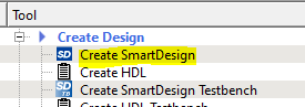
Libero project, create a new SmartDesign by double-clicking Create
SmartDesign, as shown in the following figure. Choose any name in
the Create New SmartDesign dialog.Figure 4-1. Create SmartDesign in
Libero SoC.
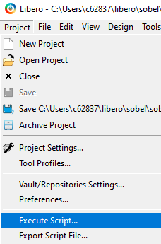
Go to the Libero
Project menu and select Execute
Script and give the path to the generated
create_hdl_plus.tcl script, as shown in the following
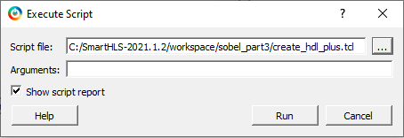
figure. Click on Run. Figure 4-2. Execute Tcl script to
instantiate SmartHLS IP component into SmartDesign.
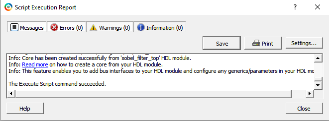
Running the Tcl script will add the SmartHLS-generated HDL+ component
sobel_filter_top and all required Verilog files, memory
initialization files, and other dependencies to the Libero project. You must see
the Execute Script command succeeded, as shown in the following figure.
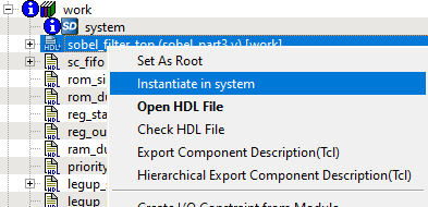
As shown in the following figure, you
can now instantiate the component in SmartDesign by right-clicking on the
sobel_filter_top HDL+ component in the Design
Hierarchy panel on the left and selecting Instantiate in
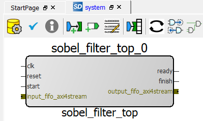
system. In the SmartDesign system, you will now see the new
sobel_filter_top_0 IP component.Figure 4-4. SmartHLS IP Component
instantiated inside SmartDesignSince the sobel_filter_top IP component used SmartHLS FIFOs
as top-level arguments, SmartHLS has automatically grouped the
output_fifo and input_fifo data/ready/valid
ports as AXI4-Stream bus interfaces.
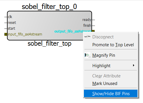
You also have the option to expose the
sub-signals under the AXI4-Stream bus. This will allow you to connect individual
ports instead of the entire bus. To do this, right click on the AXI4-Stream bus
on the SmartHLS-generated IP component and choose Show/Hide BIF
Pins. Then choose the sub-signals as appropriate.
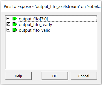
Example: As shown in the following
figure, you can right click the output_fifo_axi4stream bus
and choose to Show/Hide BIF Pins, then you select all 3 pins
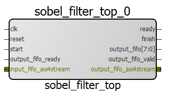
and press OK. You will now see that the
sobel_filter_top_0 IP component has an input pin for
output_fifo_ready, an output pin for
output_fifo[7:0], and an output pin for
output_fifo_valid.Figure 4-5. Expose the individual pins
contained in the output_fifo AXI4-Stream bus
The online versions of the documents are provided as a courtesy. Verify all content and data in the device’s PDF documentation found on the device product page.