
1 Step 1: Basic Implementation
In this section, use SmartHLS to compile the Sobel filter to hardware without any modifications to the C++ code.
- Start the SmartHLS IDE. On Windows, double click on the SmartHLS shortcut either in the start menu or the desktop. On Linux, ensure that $(SMARTHLS_INSTALL_DIR)/SmartHLS/bin is on your PATH, and the SmartHLS IDE can be opened by running the following command:
shls_ide. The Eclipse Launcher dialog box is displayed with a default workspace directory as shown in the following figure. - Click OK to use the default workspace for all parts of this tutorial.
Figure 1-1. Choosing a SmartHLS workspace. 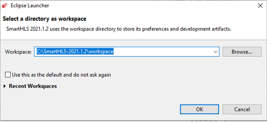 Note: Ensure that there are no spaces in your workspace path. Otherwise, SmartHLS throws an error while running synthesis.
 - Launch the SmartHLS IDE. Choose as shown in the following figure.
Figure 1-2. Create a New SmartHLS C/C++ Project 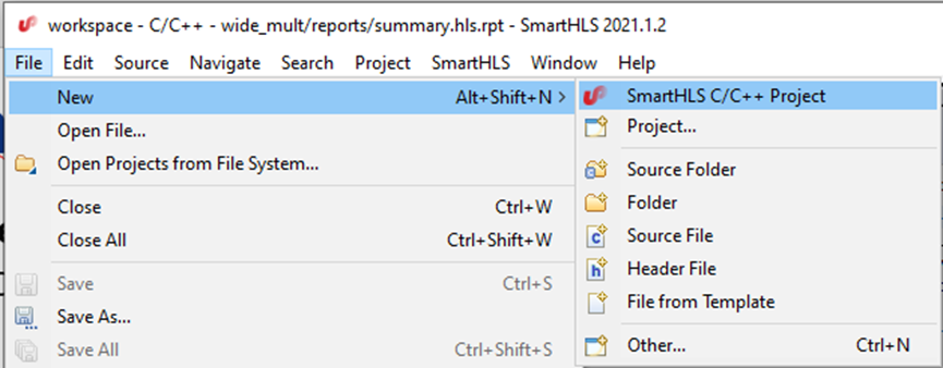
- Enter
sobel_part1as the project name as shown in the following figure. Click Next.Figure 1-3. Creating a New SmartHLS Project 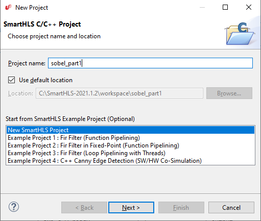
- The following figure shows leaving the Top-Level Function blank as the sobel_filter function in sobel.cpp already has a pragma to indicate the top-level function.
- Click on Add Files to import the source files for part 1 of this tutorial into the project. Navigate to where you have downloaded the tutorial files and go into the part1 directory. You can hold shift to select all three source files: input.h, output.h and sobel.cpp. After you have added the source files to the project, click Next.
Figure 1-4. Adding part1 source files into the new SmartHLS project. 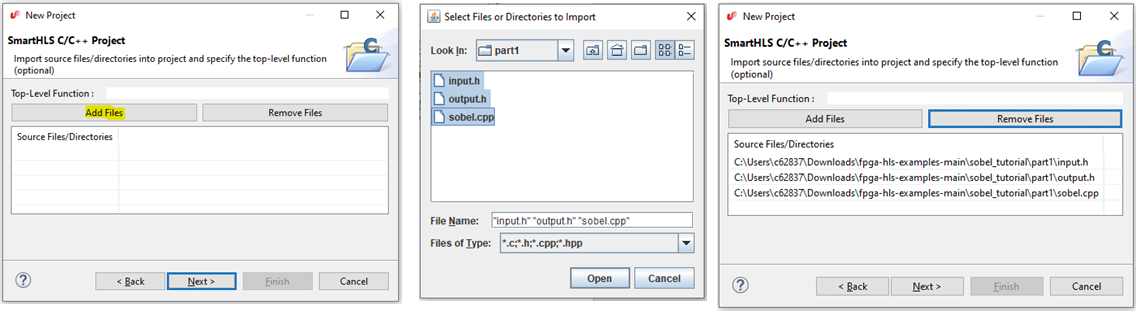
- A dialog box appears where you can specify your test bench, which is not needed for this part of the tutorial. ClickNext without changing any of the options.
- To complete the project creation, you must choose the FPGA device you intend to target. Use the selections shown in the following figure for the FPGA family choose PolarFire. For FPGA Device, you have an option to choose MPF300TS-1FCG1152I on the MPF300 Board or use another PolarFire device that is not listed.Note: For this tutorial, you will use another PolarFire device, MPF100T-FCVG484I, which can be used with a Microsemi Libero free Silver license (the bigger MPF300TS-1FCG1152I device requires the paid Gold license). To use MPF100T, choose Custom Device for the FPGA Device field, then type in MPF100T-FCVG484I in the Custom Device field. Click on Finish when you are done. It may take a few moments to create the project.
Figure 1-5. Choose an FPGA Device 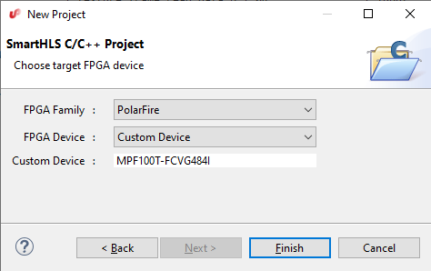
- Setup the paths to Modelsim (and Microsemi Libero for later parts of this tutorial), if this is the first time you are using SmartHLS. To setup the paths, click SmartHLS on the top menu bar, then click Tool Path Settings. The dialog opens, set the paths for ModelSim Simulator and Microsemi Libero SoC as shown in the following figure, and click OK.
Figure 1-6. SmartHLS Tool Path Settings 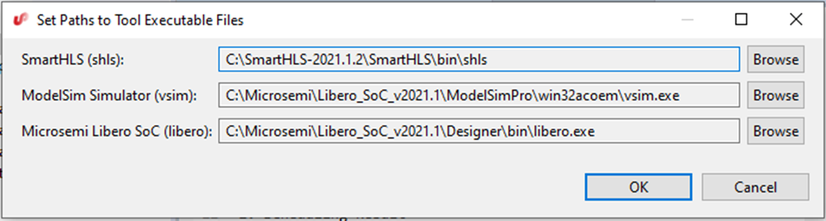
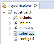
- An important panel of the SmartHLS IDE is the Project Explorer on the left side of the window, as shown in the following figure. You will use the project explorer throughout this tutorial to view source files and synthesis reports. Click on the small arrow icon to expand the sobel_part1 project. Now double click any of the source files, such as sobel.cpp, and you will see the source file appear in the main panel to the right of the Project Explorer.
Figure 1-7. Project Explorer for browsing source files and reports. 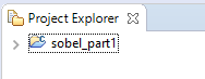
- Once a SmartHLS project is created, you should always open one of the source files (such as sobel.cpp) or double click on the sobel_part1 directory in the Project Explorer pane. This will make sobel_part1 the active project. When there are multiple projects open in the workspace, you need to click on the project in the Project Explorer pane or open a file from the project in order to make the project active before running any SmartHLS commands.The following figure summarizes the SmartHLS design flow steps.
- Create the SmartHLS project and follow a standard software development flow on the C++ (compile/run/debug).
- Apply HLS constraints (that is, target clock period) and compile the software into hardware using SmartHLS. You can review reports about the generated hardware.
- Run software/hardware co-simulation to verify the generated hardware.
- The hardware can be synthesized to our target FPGA to report the hardware resource usage and Fmax.
Figure 1-8. SmartHLS Design Flow Steps  At the top of SmartHLS, find a toolbar, as shown in the following figure, which you can use to execute the main features of the SmartHLS tool. Hover over each icon to find out its functionality. Starting from the left of the following figure, the icons are listed in the following table:
Figure 1-9. SmartHLS Toolbar Icons 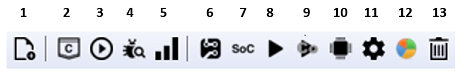 The SmartHLS commands can also be run from the SmartHLS top bar menu.
Table 1-1. Icons Icon Description 1 Add files to a project Software Development Flow 2 Compile software with GCC 3 Run software that is compiled 4 Debug the software 5 Profile software with gprof Hardware Development Flow 6 Compile Software to Hardware 7 Compile Software to Processor/Accelerator SoC 8 Simulate Hardware 9 Software/Hardware Co-simulation 10 Synthesize Hardware to FPGA Misc 11 Set HLS Constraints 12 Launch Schedule Viewer 13 Clean SmartHLS Project You can now browse through the code in sobel.cpp. In the
sobel_filterfunction, the first line#pragma HLS function topspecifies that thesobel_filterfunction is the top-level function of the project. SmartHLS will only generate a hardware module for the top-level function and all descendent functions. Thesobel_filtertop-level function contains a pair of nested loops that iterate over every pixel in the image. Inside the loop, the body is another pair of nested loops that iterate through the filter window at the current location in the image. For each pixel of the image that is not in the border, the 3x3 area centered on the pixel is convolved with Gx and Gy, then its magnitude is summed to produce the final output pixel.The main function is responsible for verifying the functionality of the
sobel_filterfunction. The grayscale (8-bit) input image is stored in the 512x512 arrayelaine_512_inputdefined in input.h, and the expected output image is stored inelaine_512_golden_outputdefined in output.h. Themainfunction passes the input image to thesobel_filterfunction and prints “PASS!” if the computed output image matches the expected output image. - Before compiling to hardware, you should verify that the C++ program is correct by compiling and running the software. This is typical of HLS design, where the designer will verify that the design is functionally correct in software before compiling it to hardware. Click on the Compile Software icon
 in the toolbar. This compiles the software with the GCC compiler. You will see the output from the compilation appearing at the bottom of the screen in the Console window of the IDE.
 - Execute the compiled software by clicking on the Run Software icon
 in the toolbar. You should see the message
 PASS!appearing in the Console window, as shown in the following figure.Figure 1-10. Console after running software execution. 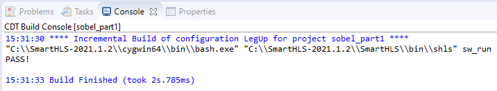
- You can now compile the Sobel filter C++ software into hardware using SmartHLS by clicking on the toolbar icon
 to Compile Software to Hardware. This command invokes SmartHLS to compile the top-level
 sobel_filterfunction into hardware. If the top-level function calls descendant functions, all descendant functions are also compiled to hardware. You can find the generated Verilog code in sobel_part1.v, as shown in the following figure.Figure 1-11. Finding the SmartHLS-generated Verilog in the Project Explorer. 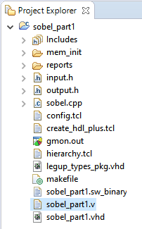
When the compilation finishes, a SmartHLS report file (summary.hls.rpt) opens. The report shows the RTL interface of the top-level module corresponding to the top-level C++ function, the number of cycles scheduled for each basic block of the function, and the memories that are used in the hardware. In this example, you will see the top-level RTL module has three interfaces, the standard Control interface that is used by any SmartHLS-generated circuit and two Memory interfaces corresponding to the input and output array arguments of the top-level
sobel_filterfunction. In the Memory Usage section of the report, there are no memories inside the generated hardware, as the input and output arrays are passed in as arguments into the top-level function. These input/output function arguments are listed as the I/O Memories table. - You can visualize the schedule and control flow of the hardware using the SmartHLS schedule viewer. Start the schedule viewer by clicking on the Launch Schedule Viewer icon
 in the toolbar. In the left panel of the schedule viewer, you will see the names of the functions and basic blocks of each function. In this example, there is only one function that was compiled to hardware,
 sobel_filter. In the Explorer pane on the left, you see thesobel_filterfunction and eight basic blocks within the functions prefixed byBB_. - Double-click on the
sobel_filterfunction in the call-graph pane, and you will see the control-flow graph for the function, similar to the following figure. The names of the basic blocks in the program are prefixed withBB_. Note that the basic block names may be slightly different depending on the version of SmartHLS you use. The basic block names are not easy to relate to the original C++ code. However, you can observe two loops in the control-flow graph, which correspond to the two outermost loops in the C++ code for thesobel_filterfunction. The inner loop contains basic blocks:BB_for_body3,BB_for_cond14_preheader,BB_for_body3_for_inc54_crit_edge, andBB_for_inc54. Try double-clicking onBB_for_cond14_preheader(if the basic block names are different from the figure, click on the left-most basic block).Figure 1-12. Control-Flow Graph for the Sobel Filter. 
- The following figure shows the schedule for
BB_for_cond14_preheader, which is the main part of the inner-most loop body. The middle panel shows the names of the instructions. The right-most panel shows how the instructions are scheduled into states (the figure shows that states 6 to 14 are scheduled for this basic block). Hold your mouse over top of some of the blue boxes in the schedule, and you will see the inputs of the current instruction become red and outputs become orange. Look closely at the names of the instructions and try to connect the computations with those in the original C++ program. You will see that there are some loads, additions, subtractions, and shifts. Close the schedule viewer ().Figure 1-13. Schedule for the Inner-Most Loop. 
- Simulate the Verilog RTL hardware with ModelSim to find out the number of cycles needed to execute the circuit – the cycle latency. Close the schedule viewer first, then click on the SW/HW Co-Simulation icon
 in the toolbar. SW/HW co-simulation will simulate the generated Verilog module,
 sobel_filter_top, in RTL using ModelSim while running the rest of the program,main, in software. The co-simulation flow allows you to simulate and verify the SmartHLS-generated hardware without writing a custom RTL test bench. You will see various messages printed by ModelSim related to loading simulation models for the hardware in the Consolewindow. The hardware may take a few minutes to simulate. You must focus on the messages near the end of the simulation, which will look like this:... # Cycle latency: 3392549 # ** Note: $finish : ../simulation/cosim_tb.sv(279) # Time: 67851010 ns Iteration: 1 Instance: /cosim_tb # End time: 15:39:12 on Jun 30,2021, Elapsed time: 0:00:41 # Errors: 0, Warnings: 0 ... Info: Verifying RTL simulation ... Retrieving hardware outputs from RTL simulation for sobel_filter function call 1. PASS! ... Number of calls: 1 Cycle latency: 3,392,549 SW/HW co-simulation: PASS
See that the co-simulation took 3,392,549 clock cycles to finish. The simulation printed
SW/HW co-simulation: PASS!which indicates that the RTL generated by SmartHLS matches the software model. The co-simulation flow uses the return value from themainsoftware function to determine whether the co-simulation has passed. If themainfunction returns 0, then the co-simulation will PASS otherwise, a nonzero return value will FAIL. Please make sure that yourmainfunction always follows this convention and returns 0 if the top-level function tests are all successful. In themainfunction of sobel_part1, also called the software test bench, we iterate over every pixel of the computed output image and verify the pixel against the expected value after calling the top-level function. A mismatch counter is incremented if a pixel is not as expected, and this counter value is returned by themainfunction. If all values match, then themainfunction will return 0. Since co-simulation printed PASS (mainreturned 0) it is verified that the generated hardware is correct. - You can also run co-simulation and launch Modelsim to show the Waveforms. From the SmartHLS top menu, select SW/HW Co-Simulation with Waveforms, as shown in the following figure.
Figure 1-14. Run SW/HW Co-Simulation with Waveforms 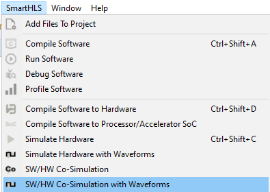
- When Modelsim opens, it will prompt, “Are you sure you want to finish?”. Select No. You can view the signal waveforms as shown in the following figure. After you are finished, close Modelsim ().
Figure 1-15. Modelsim waveforms shown during SW/HW Co-Simulation 
Libero is the name of Microchip’s synthesis, placement, routing, and timing analysis tool. SmartHLS can execute Libero to synthesize, place and route the Verilog to the Microchip PolarFire FPGA to obtain information such as the resource usage and the Fmax of this design (that is, the clock period).
- Click on the
 icon on the toolbar to Synthesize Hardware to FPGA. SmartHLS will automatically invoke Libero to create a Libero project and synthesize the SmartHLS design targeting the PolarFire FPGA device. Libero may take a while to finish. Once the command completes, SmartHLS will open the summary.results.rpt report file. SmartHLS will summarize the resource usage and Fmax results reported by Libero after place and route. You should get similar results as what is shown below. Your numbers may differ slightly, depending on the version of SmartHLS and Libero you are using. This tutorial used Libero SoC v2021.1. The timing results and resource usage might also differ depending on the random seed used in the synthesis tool flow.
====== 2. Timing Result ======
+--------------+---------------+-------------+-------------+----------+-------------+
| Clock Domain | Target Period | Target Fmax | Worst Slack | Period | Fmax |
+--------------+---------------+-------------+-------------+----------+-------------+
| clk | 10.000 ns | 100.000 MHz | 7.815 ns | 2.185 ns | 457.666 MHz |
+--------------+---------------+-------------+-------------+----------+-------------+
The reported Fmax is for the HLS core in isolation (from Libero's post-place-and-route timing analysis).
When the HLS core is integrated into a larger system, the system Fmax may be lower depending on the critical path of the system.
====== 3. Resource Usage ======
+--------------------------+---------------+--------+------------+
| Resource Type | Used | Total | Percentage |
+--------------------------+---------------+--------+------------+
| Fabric + Interface 4LUT* | 684 + 0 = 684 | 108600 | 0.63 |
| Fabric + Interface DFF* | 432 + 0 = 432 | 108600 | 0.40 |
| I/O Register | 0 | 852 | 0.00 |
| User I/O | 0 | 284 | 0.00 |
| uSRAM | 0 | 1008 | 0.00 |
| LSRAM | 0 | 352 | 0.00 |
| Math | 0 | 336 | 0.00 |
+--------------------------+---------------+--------+------------+
* Interface 4LUTs and DFFs are occupied due to the uses of LSRAM, Math, and uSRAM.
Number of interface 4LUTs/DFFs = (36 * #.LSRAM) + (36 * #.Math) + (12 * #.uSRAM) = (36 * 0) + (36 * 0) + (12 * 0) = 0.
Wall-clock time is one of the key performance metrics for an FPGA design, computed as the product of the cycle latency and the clock period. In this case, our cycle latency was 3,392,549, and the clock period was 2.346 ns. The wall-clock time of our implementation is therefore 3,392,549 × 2.346 ns = 7.959 ms. - Close the project by right clicking on the sobel_part1 folder in the Project Explorer pane, and click on Close Project.