
2.3 Kernel Configuration
The user must perform the following modifications in the Linux kernel configuration to
enable Wi-Fi support. The user must use the menuconfig to perform these
modifications if the kernel is being built separately; otherwise, the user must add the
corresponding CONFIG entries in the default defconfig file that
buildroot is configured to use.
- Go to the directory of the Linux
kernel and enter the following command:
Select the required configuration from the blue terminal to save and exit.$ make ARCH=arm menuconfig - Enable the Linux 802.11
configuration API space. Select cfg80211 - wireless configuration API from
networking support>wireless menu.Figure 2-1. Wireless Terminal Screen 
- Enable BLE by going to
Networking Support > Bluetooth subsystem support(see the following figure).Figure 2-2. Bluetooth Subsystem Support 
- Enable HCI by going to Bluetooth
device drivers (refer to the following figure).
Figure 2-3. Bluetooth Device Driver 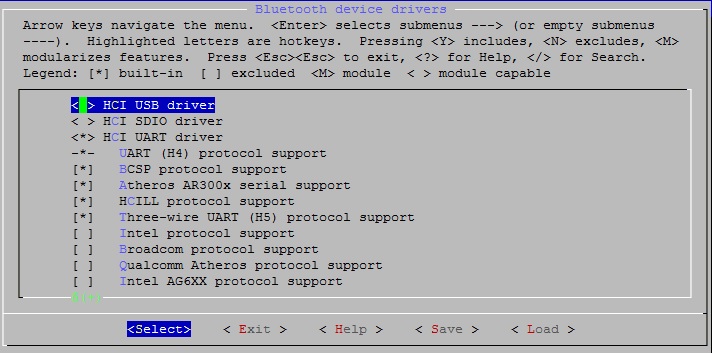
- Configure the ATWILC Driver from
Device Drivers > Network Device Support. Select the required configuration as mentioned in the following figure.Note: If the driver code is added underlinux_root/drivers/staging, themenuconfigentries are available underDevice Drivers > Staging drivers.If using only the SDIO (Secure Digital Input Output) bus, choose ‘SDIO support’ on the bus type item if WlLC1000 chipset or module is connected by SDIO bus on the platform.
Figure 2-4. Driver Driver – WILC SDIO  If using the SDIO bus with the external interrupt, there may be trouble with the SDIO interrupt on the special platform. Use the interface mixed SDIO bus and external IRQ pin to operate ATWILC1000. Select ‘Use out of band interrupt’ to send the interrupt signal to the external pin. This option appears when SDIO is chosen.
Figure 2-5. Driver Driver – WILC SDIO OUT OF BAND INTERRUPT  If using the SPI (Serial Peripheral Bus) bus, select ‘SPI support’ on the bus type item if the WlLC1000 chipset or module is connected on the platform by the SPI bus. The ‘Use out of band interrupt’ is hidden because the SPI bus demands the external IRQ pin to receive data from ATWILC1000.
Figure 2-6. Driver Driver – WILC SPI 
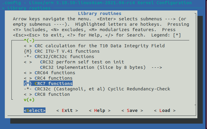
- Enable "CRC7 functions" – The
WILC driver uses the CRC7 Cyclic Redundancy Check for the SPI command
validation.
- Enable "CRC16 functions" – The WILC driver uses the CRC16 Cyclic Redundancy Check for the SPI Data validation.
