
3.2 CCL Registers Configuration
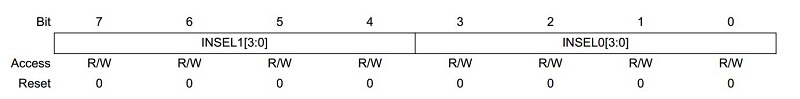
- Set LUT Control Register
B (CCL_LUTCTRLB).
- Bits
7:4 – INSEL1[3:0]: LUT n Input 1 Source
Selection
Select USART TXD as the input source.
- Bits
3:0 – INSEL0[3:0]: LUT n Input 0 Source
Selection
Select USART XCK as the input source.
- Bits
7:4 – INSEL1[3:0]: LUT n Input 1 Source
Selection
- Set TRUTH TABLE
(CCL_TRUTH).
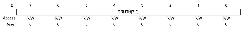
- Bits
7:0 – TRUTH[7:0]: Truth Table
Set to 0x99 (0b10011001) as XNOR logic.
- Bits
7:0 – TRUTH[7:0]: Truth Table
- Set LUT Control Register
A (CCL_LUTCTRLA).
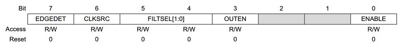
- Bit 7 – EDGEDET: Edge Detection
- Bit 6 – CLKSRC: Clock Source Selection
- Bits
5:4 – FILTSEL[1:0]: Filter Selection
Enable filter as XCK and TXD may not synchronize precisely.
- Bit 3
– OUTEN: Output Enable
Set to enable output.
- Bit 0
– ENABLE: LUT Enable
Set to enable LUT.
- Set Control Register A
(CCL_CTRLA).
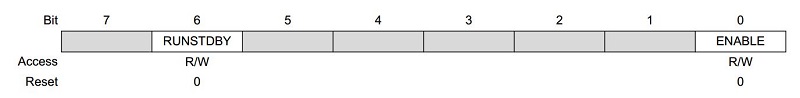
- Bit 6 – RUNSTDBY: Run in Standby
- Bit 0
– ENABLE: Enable
Set to enable CCL peripheral.