
1.5.3 Bootloader CAN-TP Demo
This section will walk through a demo of creating a bootloader project using CAN-TP as the communication protocol. The project will build a bootloader project that turns on a LED, and an application project that blinks a LED. The final step will be using the UBHA to program the application project onto the board of choice demonstrating that the CAN-TP communication is working as intended.
-
Create a new MPLAB X IDE project with the hardware of choice that can be programmed using MCC Melody.
-
Add the 16-bit Bootloader: Bootloader library (Ensure the correct version number is present using the Content Manager).
-
Select Add New CAN-TP Driver from the communication protocol dropdown. CAN-TP should be added to the project.
-
Open the Bootloader menu. Scroll to the Interrupts section and mark a Timer Interrupt and the CAN module interrupts as Keep in Bootloader. Another option would be to go to the Bootloader settings and check the Code Protect Bootloader option.
-
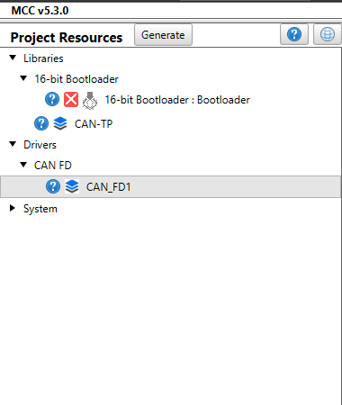
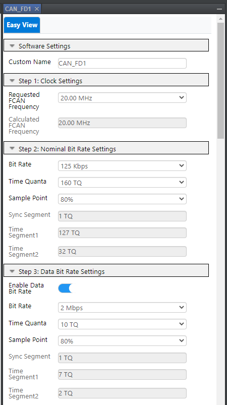
Go to the Builder view and select the CAN_FD.
-
Select Enable Data Bit Rate and set the Bit Rate to your desired speed. In this example, the bit rate is set to 2 Mbps.
-
Open the Unified Bootloader Host Application(UBHA).
-
Select the appropriate device architecture.
-
Select CAN as the communication protocol.
-
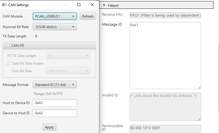
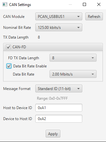
Go to Settings, and select CAN to open the CAN Settings window.
-
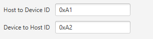
Note the Host to Device ID and Device to Host ID.
-
Go the CAN_FD window in MPLAB X, scroll down to the FIFO section and add the Host to Device ID noted before to the Message ID text box.
-
In the Pin Grid View, select a pin connected to a LED on the device as the output to ensure that it lights up.
-
In the same view, select device appropriate the CAN TX and RX pins.
-
Click Generate. All files should generate successfully.
-
Go to MCC Generated Files/boot/boot_demo.c file.
-
Add code to set a LED of choice to high. For the demo board in this example, pins.h is imported, the code is added inside the BOOT_DEMO_Tasks() function and IO_RE0_SetHigh() is used turn on LED0.
-
Next, disable the timer being used by the CAN-TP module before the start of the application.
-
Add the following lines inside the BOOT_DEMO_TASKS function. As this code is an example that uses the TMR1. Modify the code to ensure it is in accordance with the timer being used on your device.
if(inBootloadMode == false)
{
    /* NOTE: Before starting the application, all interrupts used
    * by the bootloader must be disabled. Add code here to return
    * the peripherals/interrupts to the reset state before starting
    * the application code. */
    #warning "All interrupt sources and peripherals should be disabled before starting the application.  Add any code required here to disable all interrupts and peripherals used in the bootloader."
    TMR1_Stop();
    BOOT_StartApplication();
}
For the final step, download the project onto the device.-
Click Clean and Build Main Project. The project should build successfully.
-
Click Make and Program Device Main Project and verify that the LED of choice turns on.
-
The Bootloader project is now ready and it's purpose is turning on a LED on the board.
-
-
Create a new project and add the 16-bit Bootloader:Application library (Ensure the correct version number is present using the Content Manger).
-
Add the Bootloader project created above. Verify that the details such as the verification scheme are showing up are as expected.
-
Select another LED pin as output in the Pin Grid View. This pin must not be the same LED as the one the bootloader project is using.In this example, we are using RE1 to turn on LED1.
-
Click Generate. All files should generate successfully.
-
Add the following code to the main.c file to periodically blink a LED. This code is an example, ensure that the code is modified for the device and the I/O pin being used.
int main(void)
{
    unsigned int counter = 0;

    SYSTEM_Initialize();

    while(1)
    {
        if((counter++ % 0x8000) == 0){
            IO_RE1_Toggle();
        }
    }
}
For the final step, download the project onto the device.-
Click Clean and Build Main Project. The project should build successfully.
-
Click Make and Program Device Main Project and verify that the LED is blinking.
-
The application project is now ready and it blinks a LED on the board.
-
-
Ensure that the Bootloader is programmed into the device.
-
Open the Unified Bootloader Host Application(UBHA).
-
Select the appropriate device architecture.
-
Select CAN as the communication protocol.
-
Go to Settings, and select CAN from the dropdown to open the CAN Settings window.
-
Verify the CAN Module is present.
-
Check the CAN-FD checkbox.
-
Check the Data Bit Rate Enable box.
-
Set the data bit rate to the same bit-rate you set in Step 6 while making the Bootloader. In this example, that corresponds to 2.00 Mbits/s.
-
Ensure that the rest of the CAN settings match the Bootloader's CAN settings.Verify the Message ID settings for the CAN_FD in MPLAB are the same as the UBHA settings.
-
Click Apply.
-
Go to File, and load the hex file for the application project that was built above.
-
Click Read Device Settings. The application start and end addresses should populate appropriately.
-
Click Program Device. Verify that the application project is loading on the board and that the LED is blinking as expected.
-
The application has been loaded onto the board using CAN as the communication protocol.