3 Host Read/Write Data Using Interrupts
In this use case, the microcontroller is configured in I2C Host mode using the MSSP1 instance of the MSSP peripheral, and communicates with the client MCP23008, an 8-bit I/O expander that can be controlled through the I2C interface.
The extended pins are set as digital outputs with an I2C write operation in the client’s I/O Direction (IODIR) register.
After the pins are set, the program will repeatedly:
- Set the pins to the value of the
datavariable, with an I2C write operation in the GPIO register. - Read from the GPIO register, with an
I2C read operation and save the value into the
datavariable. - Invert the bits in the
datavariable to write another value into the GPIO register in the next loop.
-
To transmit data as an I2C host, the following sequence must be implemented:
- Establish connection to I2C
Device
- Generate the Start condition by setting the SEN bit in the SSPxCON2 register.
- The SSPxIF flag in the PIR3 register is set by hardware on completion of the Start condition and must be cleared by software.
- Load the client address into the SSPxBUF register.
- Clear SSPxIF flag in the PIR3 register indicating that the host is ready for another byte and must be cleared by software.
- Check the ACKSTAT bit in the SSPxCON2 register.
- Write the desired register to client
device
- Load the register address in the SSPxBUF register.
- The SSPxIF flag in the PIR3 register is set by hardware indicating that the client is ready for another byte and must be cleared by software.
- Check the ACKSTAT bit in the SSPxCON2 register.
- Write a byte of data to the client
device
- Load the data in the SSPxBUF register.
- The SSPxIF flag in the PIR3 register is set by hardware indicating that the client is ready for another byte and must be cleared by software.
- Check the ACKSTAT bit in the SSPxCON2 register.
- End I2C connection
- To end the transmission, generate the Stop condition by setting the PEN bit in the SSPxCON2 register.
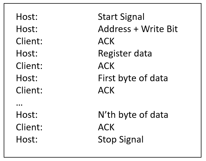
Figure 3-1. Step-By-Step Description of Host Writing N bytes to a Client Device Over I2C 
- Establish connection to I2C
Device
-
To receive data as an I2C host, the following sequence must be implemented:
- Establish connection to I2C
Device
- Generate the Start condition by setting the SEN bit in the SSPxCON2 register.
- The SSPxIF flag in the PIR3 register is set by hardware on completion of the Start condition and must be cleared by software.
- Load the client address into the SSPxBUF register.
- Clear SSPxIF flag in the PIR3 register indicating that the host is ready for another byte and must be cleared by software.
- Check the ACKSTAT bit in the SSPxCON2 register.
- Receive and ACK data byte (Repeat
N-1 times)
- Set the RCEN bit to enable the Receive mode.
- Clear SSPxIF flag in the PIR3 register indicating that the host is ready for another byte and must be cleared by software.
- Read data from the SSPxBUF register.
- Send an Acknowledge bit to tell the device to send the next byte.
- Clear SSPxIF flag in the PIR3 register indicating that the host is ready for another byte and must be cleared by software.
- Receive last byte in frame
- Set the RCEN bit to enable the Receive mode.
- The SSPxIF flag in the PIR3 register is set by hardware and must be cleared by software.
- Read data from the SSPxBUF register.
- Send a Not Acknowledge bit to stop receiving bytes.
- Clear SSPxIF flag in the PIR3 register indicating that the host is ready for another byte and must be cleared by software.
- To end the transmission, generate the Stop condition by setting the PEN bit in the SSPxCON2 register.
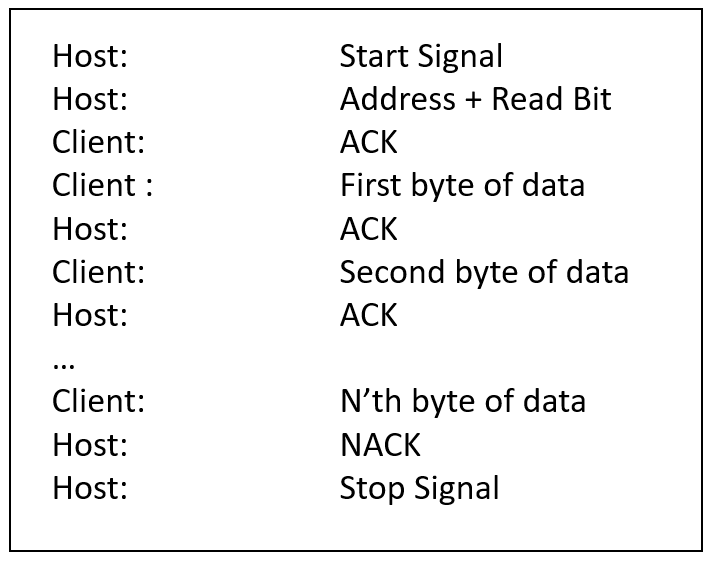
Figure 3-2. Step-By-Step Description of Host Reading N Bytes From a Client Device Over I2C 
- Establish connection to I2C
Device
Note: For a reliable I2C operation,
external pull-up resistors must be added. Refer to TB3191 - I2C Master Mode for more
details.
