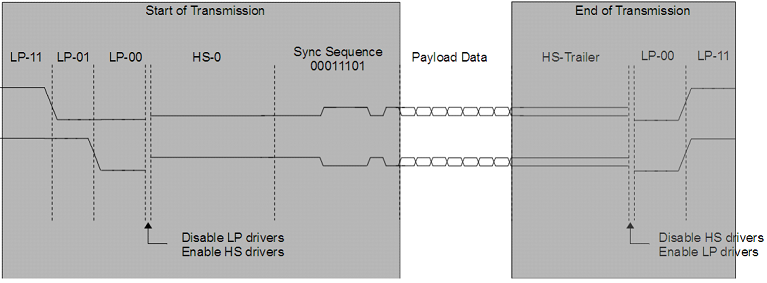
High-Speed Data Transfer Mode
High-speed data transfer occurs in bursts. The lane is in High-Speed mode only during these bursts. A high-speed burst must start from and return to a Stop state (Control mode).
High-speed data bursts are independent for each lane, which means that each data lane can start and end a high-speed transmission independently of the state of the remaining data lanes.
A burst contains the low-power initialization sequence, the high-speed data payload, and also the end of transmission sequence.

High-Speed mode request is initiated by the DSI host. This request is processed differently for clock and data lanes.
For a clock lane, the high-speed request is followed by the transmission of a low-power sequence that represents this request for the receiver side (a lane high-speed request). Only after generating this sequence, the low-power driver is disabled, and the high-speed driver enabled. After the time necessary to settle, the transmission of the high-speed DDR clock starts.
For a data lane, the high-speed request starts with a lane high-speed request and, in addition, extends the payload data with a leader and a trailer sequence that allows for the receiver synchronization. The transmission of such sequence requires the existence of a valid high-speed clock signal in the clock lane.
When the high-speed request is disabled, each lane exits High-Speed Data Transmission mode. It is important that a clock lane is in High-Speed mode during the complete high-speed data transmission state of all the lanes. The clock lane must enter High-Speed mode before a high-speed data transmission begins and it must not leave this state before all the lanes finish their respective high-speed data transmission bursts.
The operation sequence when exiting High-Speed mode is also different for data and clock lanes.
For a clock lane, high-speed transmission always ends with an HS-0 state, followed by the disabling of the high-speed driver, and enabling of the low-power driver. As for a data lane, the transmission ends with the differential state opposite to the last bit transmitted, followed by the disabling of the high-speed driver, and enabling of the low-power driver.
