
3.4 Execution Flow
The first time, the Secure Firmware Upgrade application is programmed using the Host and Bootloader application on the host and client. The following topic discusses the MPLAB Harmony v3 Host and Bootloader application system-level execution flow.
Host Application System Level Execution Flow
The following figure illustrates the Bootloader system-level execution flow for programming the target application for the first time.
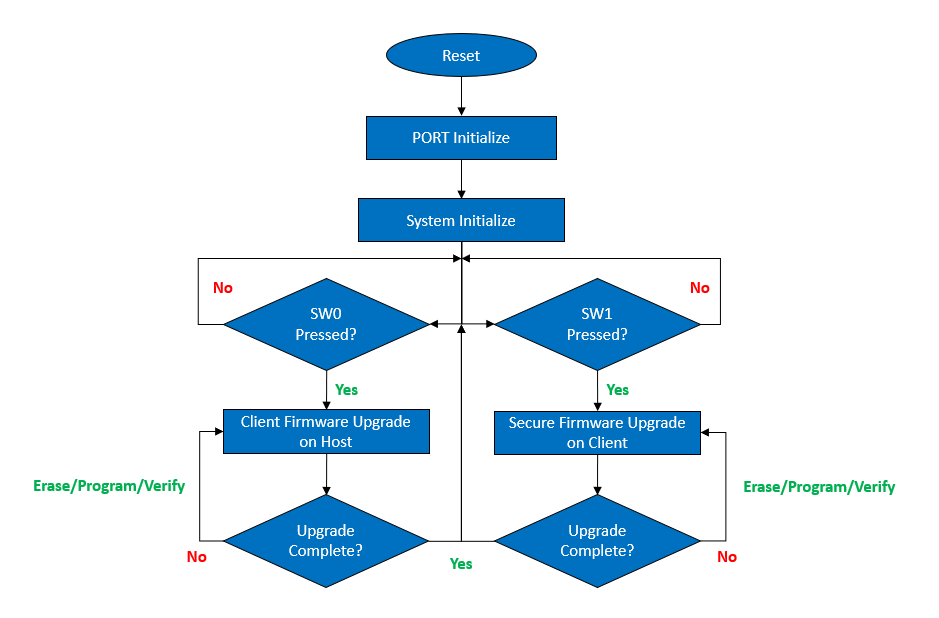
The Host application follows this sequence of execution:
- The Host MCU is designed to wait for a button press to initiate either a client firmware upgrade on the host or a secure firmware upgrade on the client.
- When the SW0 button is pressed, the Host MCU enters the Client firmware upgrade mode. In this mode, it receives the client firmware from the Host PC through UART.
- When the SW1 button is pressed, the Host MCU enters the secure firmware upgrade mode. In this mode, it transfers the client firmware to the Client through UART.
- Once the firmware has been successfully received or transferred, the Host MCU returns to its initial state.
Bootloader Application System Level Execution Flow
The following figure illustrates the Bootloader system-level execution flow for programming the target application for the first time.
The bootloader application follows this sequence of execution:
- When the device is reset, the bootloader code starts running. If there are no conditions for entering firmware upgrade mode, the bootloader will run the user application after initializing the ports.
- The bootloader enters the firmware upgrade mode when the following trigger is
detected:
- Using the onboard switch as a bootloader trigger pin to force entry to the bootloader at device reset.
- Check for a specific bootloader request pattern (0x5048434D) from the first 16 bytes of the SRAM to force entry to the bootloader at device reset.
- The bootloader performs Erase, Program, and Verify operations while in the firmware upgrade mode.
- Once the entire firmware is received, the bootloader loads the new firmware by initializing a software reset.
Target Application System Level Execution Flow
After the Target application is successfully programmed through the bootloader, the bootloader loads the target application, and the CPU starts executing it.
The following flow diagram illustrates the execution of the Target application.
The sequence of execution for the target application is as follows:
- When the device is reset, the bootloader loads the target application from the application region of the Secure Flash Memory.
- The target application initializes the system and prints the startup message on the serial console.
- The onboard LED0 toggles every second until switch SW0 is pressed to enter firmware upgrade mode, triggering a system reset to run the bootloader application by changing the trigger pattern in the SRAM.