4.2.6 UART Command/Response Frame Reception
Receiving UART command/response frames involves the following capabilities:
- Detecting the start of UART command/response frames.
- Detecting the end of UART command/response frames.
- Verifying the command/response frame checksum.
- Notifying the Firmware Update Protocol Layer of certain types of command/response frame reception errors (Transport Errors).
Additionally, this section defines a command-response frame reception algorithm with the following goals:
- Allow resynchronization of command/response frame reception to the UART byte stream after some form of data corruption.
- Limit the number of error responses to invalid or corrupted commands.
4.2.6.1 Details of Frame Reception
The following sections detail detection of the Start-Of-Frame and End-Of-Frame, as well as the related Receive Window.
4.2.6.1.1 Start-Of-Frame
Since all UART command/response frames start with the Start-Of-Frame (SOF) reserved code, this code is used as a synchronization mechanism. When a SOF is received, the following actions are taken:
- Any partially received UART command/response frame is discarded.
- The receive window is opened to allow incoming bytes to be processed as part of a command or response frame.
4.2.6.1.2 End-Of-Frame
All UART command/response frames end with the End-Of-Frame (EOF) reserved code. The EOF signals that a complete command or response has arrived and is ready for further processing. When an EOF is received, the following actions are taken:
- The receive window is closed.
- The command or response checksum is verified.
- If the checksum is valid, the command/response is passed on for further processing.
- If the checksum is invalid, the command/response frame is discarded and a Transport Error is signaled to the Firmware Update Protocol Layer.
4.2.6.1.3 The Receive Window
When byte streams get corrupted and command/response frame synchronization is lost, there is the potential to place invalid data into the receive processing algorithm.
To help reduce the chances of processing corrupted data streams, the MDFU UART Transport Layer implements a receive window which gates when received data is processed.
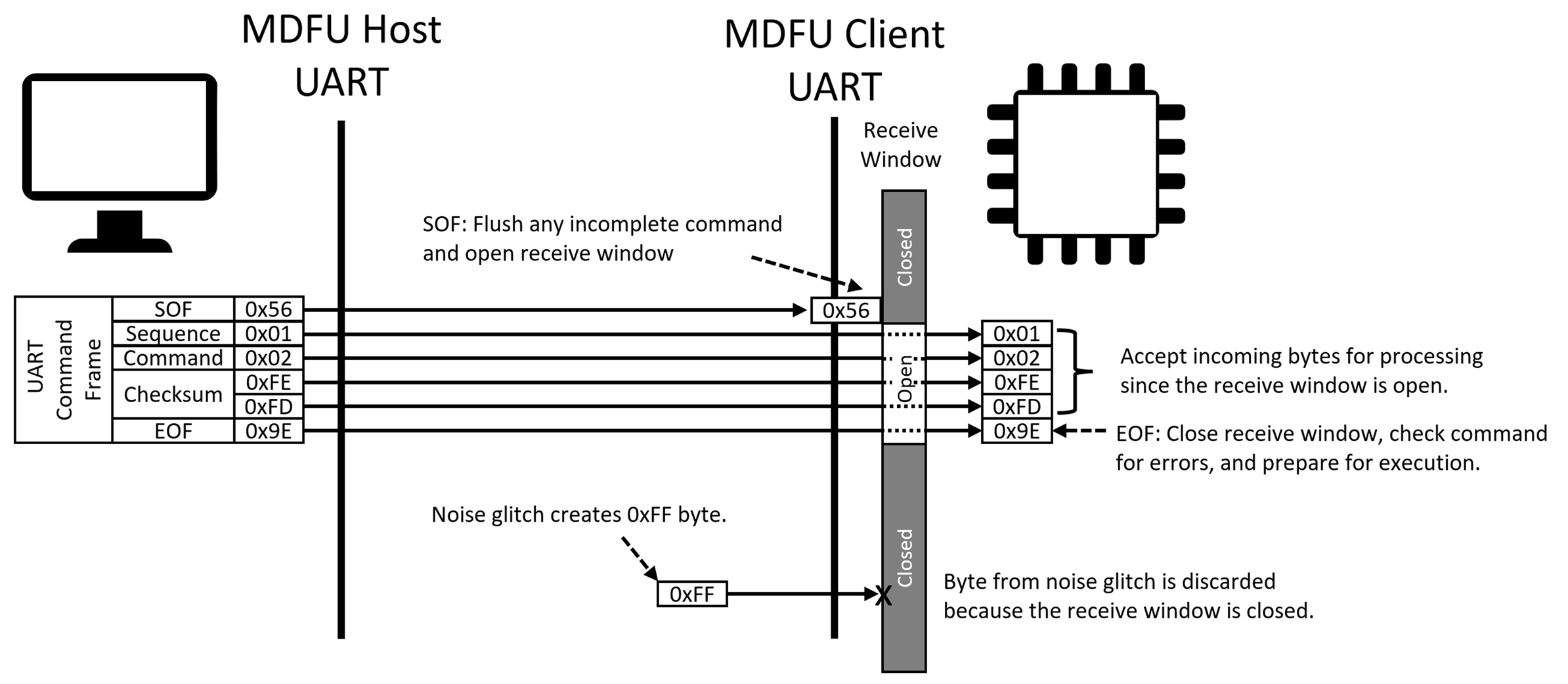
When the receive window is closed, incoming bytes are discarded and not processed. When the window is open, incoming bytes are accepted. The Start-Of-Frame code is the only code that is accepted when the window is closed and it is used to open the window. The End-Of-Frame code and certain types of detected errors are used to close the window.
The following figure shows an example command frame where the Start-Of-Frame opens the receive window. Incoming bytes are then accepted as part of the MDFU UART command/response frame. The End-Of-Frame code closes the window and prepares to process the command. The figure also shows how the closed receive window can reject a noise glitch which causes a 0xFF byte.

4.2.6.2 Incoming Byte Processing Algorithm
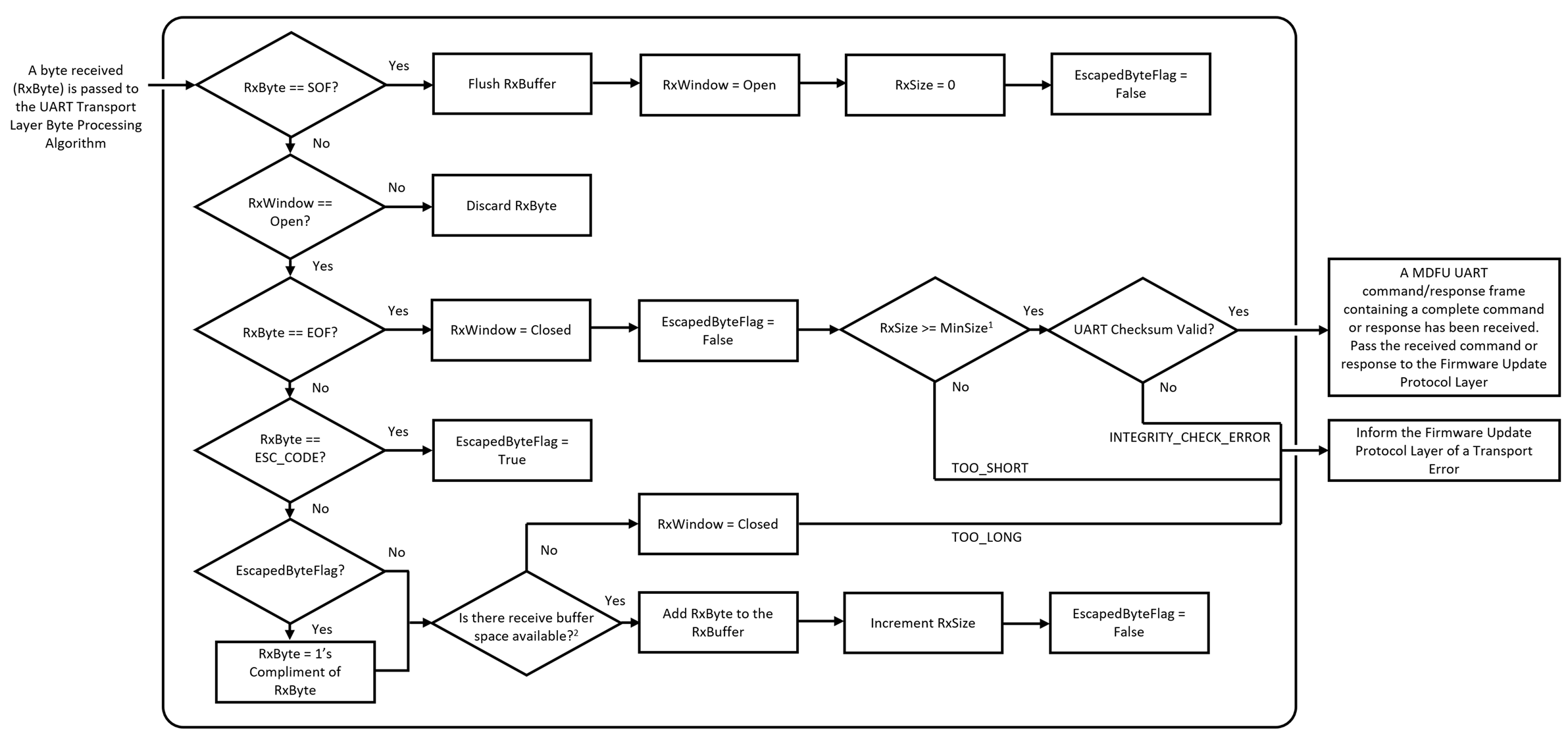
The following algorithm specifies how the incoming byte stream must be processed to properly receive commands/responses, verify their integrity, and react to various error conditions.

| Figure Notes | |
| Note 1: | MinSize = 4; MinSize = 1-byte Sequence + 1-byte Command Code or 1-byte Status + 2-byte checksum = 4 bytes |
| Note 2: |
For commands, there is space available if RxSize < (MaxCommandDataLength + 4): 1-byte Sequence + 1-byte Command Code + MaxCommandDataLength Data Payload + 2-byte checksum = MaxCommandDataLength + 4 For responses, hosts must allocate sufficient size response buffers for the clients they are updating and protect from overflowing their response buffers. See the Command-Response Pairs section of the specification for more information on response sizes. |
4.2.6.3 UART Driver Buffer Sizing
The incoming byte processing algorithm operates on one byte at a time. Incoming bytes can be processed fairly quickly by this algorithm as they come in.
The timing requirements associated with pulling bytes out of the UART Driver and feeding them into the Transport Layer Incoming Byte Stream Processing Algorithm is a function of how much buffering is present in the UART driver. Individual system designers can decide how much buffering inside the UART driver makes sense based on the system resources (Flash/RAM/Processing) available in a design.
Implementations that are memory constrained and can allocate enough processing priority to process incoming bytes on the fly as they arrive may elect to have little to no buffering in the UART driver, as shown below.

Other systems may have higher priority tasks that are running at the same time as the MDFU tasks and may only be able to provide limited timing priority and/or processing cycles to the UART Driver and MDFU tasks. In these systems, adding buffering inside the UART driver as shown in the figure below can give the system more time to do other things before it needs to come back and get bytes from the UART buffer to pass them into the Transport Layer incoming byte stream processing algorithm. Sizing this UART reception buffer is left to the individual host and client designer.

Please consider the following two points when sizing the client UART reception buffer:
- If the client UART reception buffer is smaller than the size of any command, the time frame associated with having to remove bytes out of the UART buffer to prevent it from overflowing is related to the size of the buffer and the data rate of the UART.
- If the client UART reception buffer is sized to be able to hold the largest MDFU UART command frame size, then the timing requirement to remove bytes from the UART buffer is no longer determined by the size of the buffer and the data rate of the UART. Rather, the timing requirement is now set by the need to satisfy the command time-out parameter requirement. This time-out parameter can be configured to be a long period of time which can allow the MDFU tasks to run as very low-priority background tasks with very slow timing requirements. See the Maximum UART Command/Response Frame Size section for details on how large the UART buffer needs to be sized to receive an entire UART command frame.
Similarly, please consider the following two points when sizing the host UART reception buffer:
- If the host UART reception buffer is smaller than the size of any response, the time frame associated with having to remove bytes out of the UART buffer to prevent it from overflowing is related to the size of the buffer and the data rate of the UART.
- If the host UART reception buffer is sized to be able to hold the largest UART response frame size that the attached client sends, then bytes don’t need to be removed from the UART receive buffer as a response is arriving to avoid overflowing the buffer. This increases the amount of time that the host can work on other things before needing to service the MDFU tasks which can be helpful for hosts that are running other high priority tasks.
