4.2.3 UART Command/Response Framing
This section defines the MDFU UART framing mechanism which accomplishes the following goals:
- Identifies the start of a command or response in the UART byte stream.
- Identifies the end of a command or response in the UART byte stream.
- Provides a mechanism for detecting corruption of commands and responses.
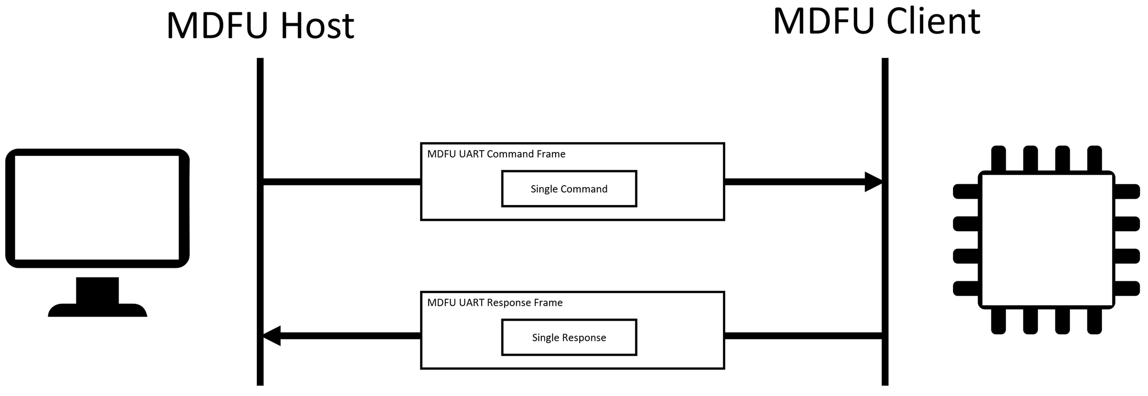
4.2.3.1 One Command or Response per UART Command/Response Frame
MDFU UART command/response frames are used to transport commands from the host to the client and responses from the client to the host. MDFU UART command/response frames always contain a single complete command or single complete response in its entirety. Commands and responses are never split across multiple MDFU UART command/response frames. Multiple commands and multiple responses are never put into a single MDFU UART command/response frame.
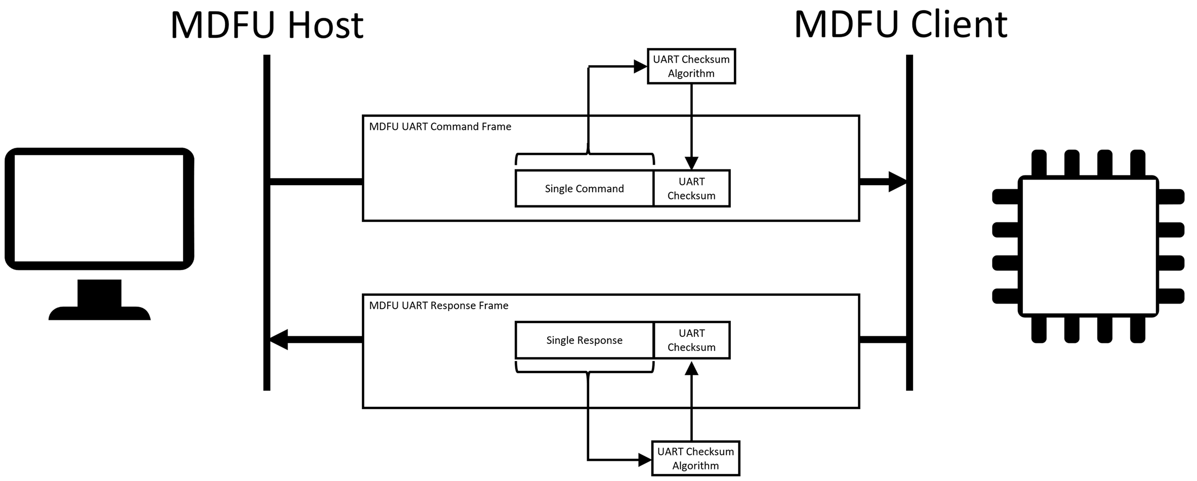
4.2.3.2 UART Checksum for Command/Response Frame Corruption Detection
The MDFU UART Transport Layer has been designed to operate over a UART Configuration which does not provide any error detection included as part of the UART physical layer. The MDFU UART Transport Layer appends a 16-bit checksum to the end of the command/response to provide a mechanism for detecting command/response corruption.
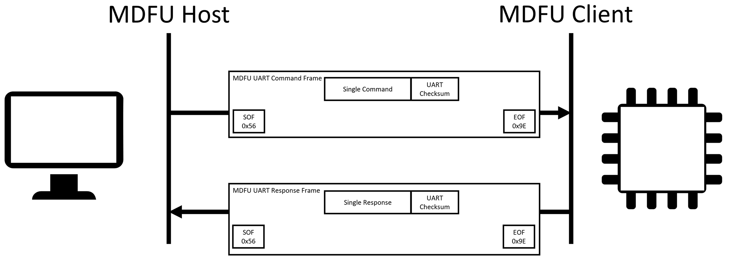
4.2.3.3 Start-Of-Frame and End-Of-Frame
The MDFU UART Transport Layer reserves the byte code 0x56 to mark the start of a UART command/response frame. Any and every time a 0x56 is detected in the UART byte stream, this means that a UART command or response frame is starting. The code 0x56 is not allowed to exist anywhere else in the byte stream.
The MDFU UART Transport Layer reserves the byte code 0x9E to mark the end of a UART command/response frame. Any and every time a 0x9E is detected in the UART byte stream, this means that a UART command or response frame is ending. The code 0x9E is not allowed to exist anywhere else in the byte stream.
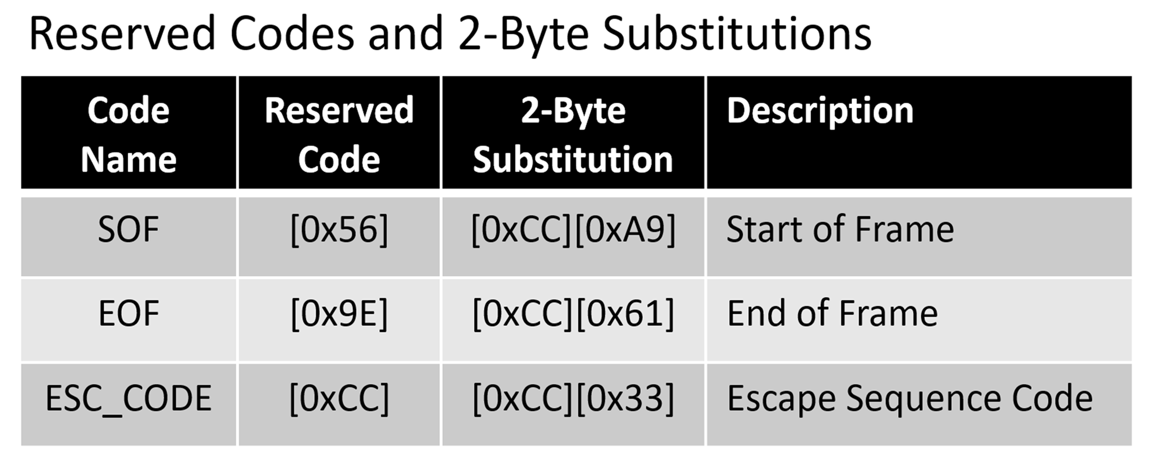
4.2.3.4 Reserved Code Substitutions
Commands, responses, and UART checksums may be composed of bytes containing the codes 0x56 and 0x9E, but those codes are not allowed to be transmitted in the byte stream except to mark the start or end of a command/response frame. Whenever a 0x56 or 0x9E are present in the commands, responses, and UART checksums, those bytes must be substituted with an alternative representation of those reserved byte codes.
- The first byte code in the two byte sequence is the escape code (0xCC).
- The second byte code in the two byte sequence is the one’s compliment of the code being represented.
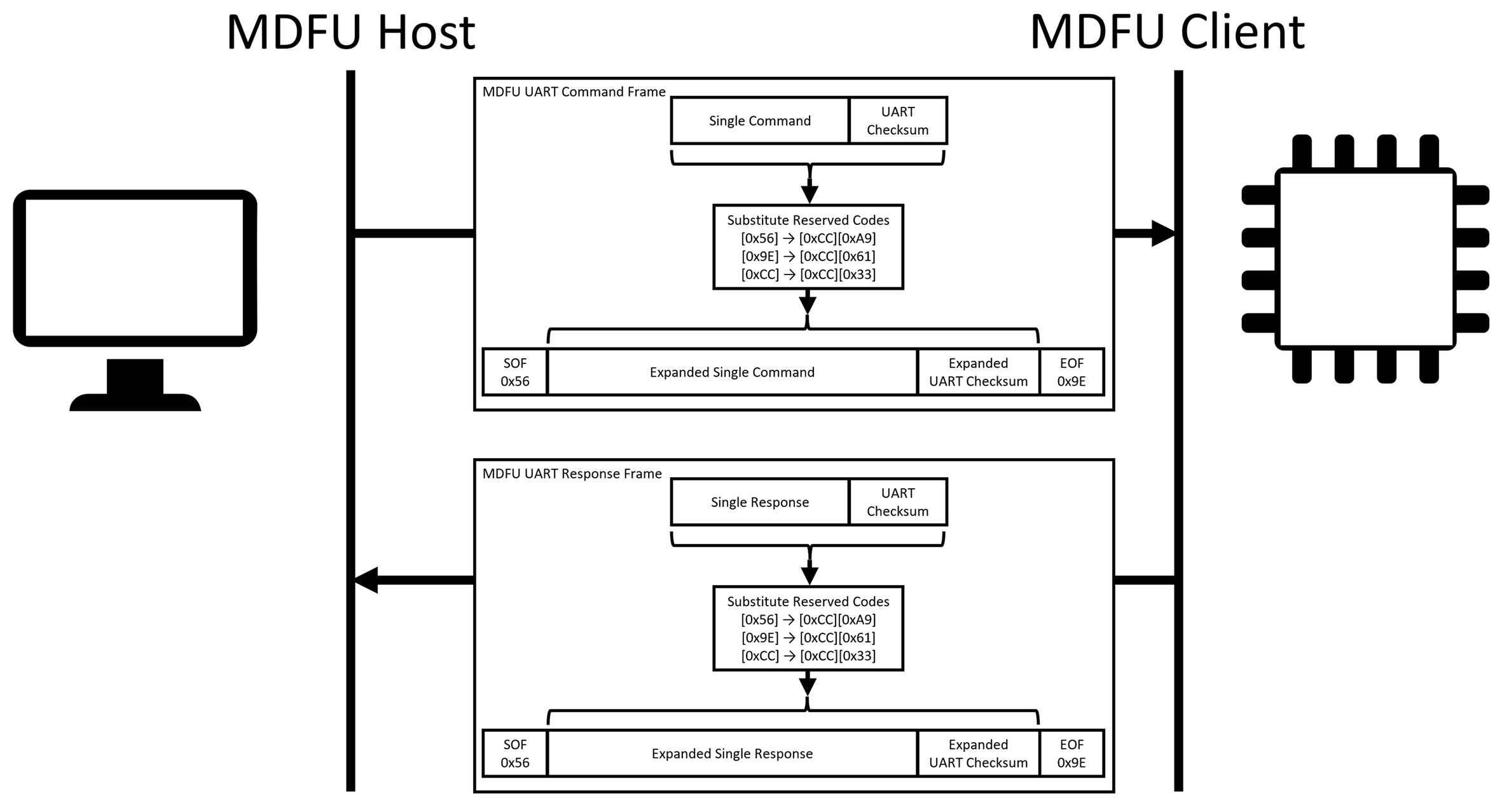
The following figure shows the reserved codes along with the 2-byte substitutions for those reserved codes.
The following figure shows how commands, responses, and checksums go through the reserved code substitutions when being placed in the MDFU UART command/response frame.
This is the final form of the command and response frames which are transmitted over the UART byte stream.