
5.5 SOF Detection and Wakeup Configuration
The USART start-of-frame (SOF) detector can wake up the CPU from Standby Sleep mode when
it detects a Start bit. In Standby Sleep mode, the internal fast start-up oscillator
must be selected as the GCLK_SERCOMx_CORE source. The application
enters the Standby Sleep mode, and the PC key press character will wake up the device
from the Sleep mode and displays the character on the terminal.
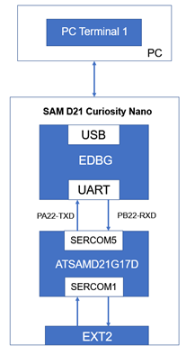
This application uses only one SAM D21 Curiosity Nano Evaluation Kit connected to the PC terminal through EDBG. In this section, only SOF detection and wakeup configuration part will be explained whereas the remaining availabe in the Basic Configuration section.
To add and configure MPLAB Harmony components using the MCC, follow these steps:
- To create the project, see SAM D21 Curiosity Nano Evaluation Kit.
- Click and expand SERCOM5 and
then select Enable Run in Standby, and then click Generate.
Figure 5-64. Configuration Options 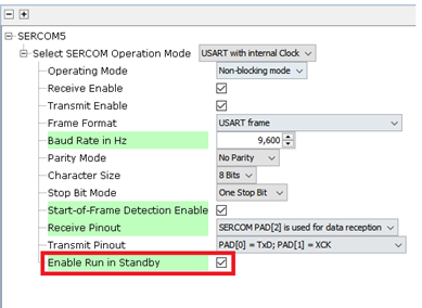
- Add the following code outside the
main() function:
#define RX_BUFFER_SIZE 1 volatile bool rx_done = false; uint8_t edbg_rx_data; volatile bool tx_done = false; void APP_SERCOM_5_WriteCallback(uintptr_t context) { tx_done = true; } void APP_SERCOM_5_ReadCallback(uintptr_t context) { if((SERCOM5_REGS->USART_INT.SERCOM_INTFLAG & SERCOM_USART_INT_INTFLAG_RXS_Msk) == SERCOM_USART_INT_INTFLAG_RXS_Msk) { SERCOM5_REGS->USART_INT.SERCOM_INTFLAG |= (uint8_t)SERCOM_USART_INT_INTFLAG_RXS_Msk; } rx_done = true; } void usart_send_string(const char *str) { SERCOM5_USART_Write((void *)&str[0], strlen(str)); } - In the following code example, the
tx_donebecomes true once the write function (which is happening inAPP_SERCOM_5_Writecallback ()is completed andrx_donebecomes true once read function (APP_SERCOM_5_Raedcallback ()is completed. Also, set the RXS flag if the value ofRXS_MskandSERCOM_INTFLAGequalsRXS_Msk. The functionusart_send_string()is used to send strings to the console.Figure 5-65. Implementation of SOF Detection and Wakeup Configuration - Example 1 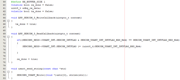
- Add the following code inside the
main()
function:
/* Initialize all modules */ SYS_Initialize ( NULL ); SERCOM5_REGS->USART_INT.SERCOM_INTENSET = (uint8_t)SERCOM_USART_INT_INTENSET_RXS_Msk; // EDBG SERCOM Read and Write Callback SERCOM5_USART_ReadCallbackRegister(APP_SERCOM_5_ReadCallback, 0); SERCOM5_USART_WriteCallbackRegister(APP_SERCOM_5_WriteCallback, 0); // Read request for EDBG SERCOM5_USART_Read(&edbg_rx_data, RX_BUFFER_SIZE); - In the following figure, set the particular RXS interrupt, and the callback
registers are called as seen in the basic configuration. Also, a read request is
also given.
Figure 5-66. Implementation of SOF Detection and Wakeup Configuration - Example 2 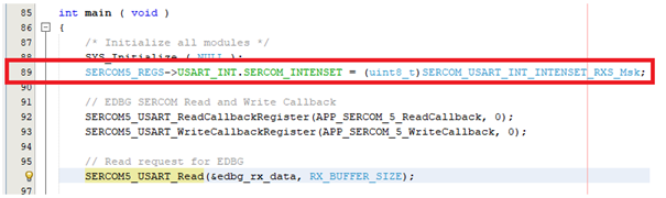 Note: In SOF detection and wakeup configuration only SERCOM5 (EDBG) is used.
 - Add the following code inside the
whileloop:if (!rx_done) { tx_done = false; usart_send_string("\r\n Device entered into standby sleep mode"); while(!(SERCOM5_REGS->USART_INT.SERCOM_INTFLAG & SERCOM_USART_INT_INTFLAG_TXC_Msk)); // Enters standby sleep mode. PM_StandbyModeEnter(); } while(!rx_done); tx_done = false; usart_send_string("\r\n Character received after wakeup :"); while(!tx_done); tx_done = false; SERCOM5_USART_Write(&edbg_rx_data, RX_BUFFER_SIZE); while(!tx_done); rx_done = false; SERCOM5_USART_Read(&edbg_rx_data, RX_BUFFER_SIZE); SYS_Tasks ( ); } - In the following figure, when a
character is entered, it wakes up from Sleep mode and print the character that is
entered. Until the TXC is false (i.e., until the transmission is complete) it loops
in the while loop itself. When it becomes true (i.e., once the transmission is
complete) it enters Standby Sleep mode.
Figure 5-67. Implementation of SOF Detection and Wakeup Configuration - Example 3 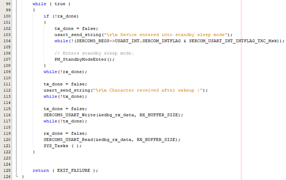
Figure 5-68. SERCOM USART – SOF Detection and Wake-up Configuration Output 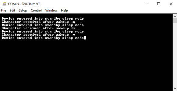 Note: The SOF detection and wakeup configuration is not available in the SAM E70/S70/V7x family of devices.