
1 MCC Melody Timer Example Component
This document provides a guide to the MCC Melody Timer Example component. It covers several Timer Driver use cases.
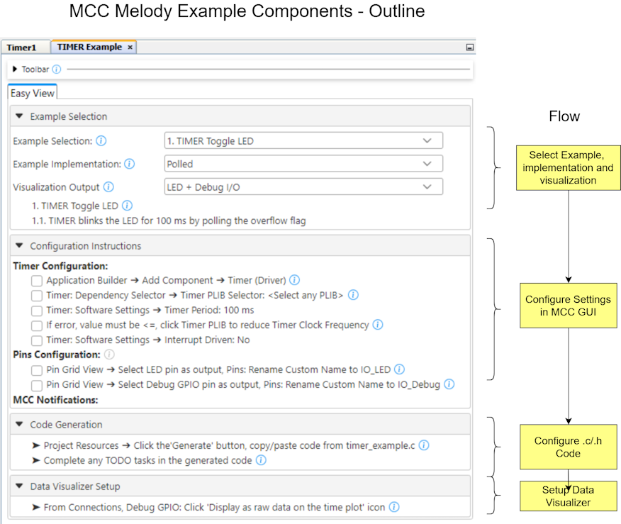
For the Timer Driver, the Polled and Interrupts with callbacks are very similar. Since both implementations use a callback, the main difference is how the callback is called. In the polled implementation, this is via a task( ) routine, while for the interrupt-based implementation, this is done via the Interrupt Service Routine (ISR). See Task Routines for more information.
A visualization option using the Debug GPIO on the MPLAB Data Visualizer is provided, in order to verify the timing. Guidance is provided on using the MCC Melody Application Builder to add and configure components for the application.
Once the MCC Melody Components are configured, you will be able to
generate the main.c source code, corresponding to the given Example,
Implementation and Visualization.
1.1 Introduction to the MCC Melody Example Components
Complete projects, available in MPLAB® Discover or GitHub, are specific to a board or microcontroller. However, the current project can be recreated on a range of supported microcontrollers by following the steps in the example component.
To explore what an example component is, as well as the difference between example and implementation, see MCC Melody Example Components - The Basics.
Example Components are related to MCC Melody Design Patterns for Control Flow,
which shows different standard ways to organize the main.c and other
application-level files, such as Polling, Interrupt and Callback, or State Machine
Design Patterns. Users might be familiar with each of these patterns, but:
- What support does MCC Melody provide for each?
- What are the recommended ways of building on the MCC Melody generated code?
1.2 MCC Melody Help Map
This diagram shows the MCC Melody Builder view, with an example project open, where links are provided for more information on a range of topics. Read the questions to find one that matches what you are looking for. The adjacent links will open online references or video training (courses) to get you familiar with different pieces of the MCC Melody and MPLAB® Tools Ecosystem.
1.2.1 MCC Melody Builder, GUI

1.2.2 Tools Ecosystem Context
Where does MCC Melody fit into the MPLAB Tools Ecosystem?
