
5 Pin Configuration
5.1 Pins Selection: Finding Schematics
To select any of the required pins for a given example, refer to the schematic of the board you are using. Examples can often be run on a range of hardware, selecting appropriate pins for a LED, Analog Input (ANx), UART Tx/Rx, etc.
If the Curiosity Nano platform is being used, the following guidelines will be useful.
When plugging in a Curiosity Nano evaluation kit, MPLAB® X IDE will open the Kit Window tab, which contains a number of useful links for the particular board that you have.
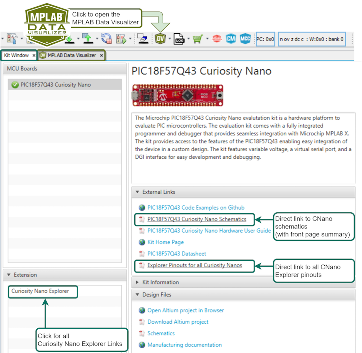
Click the Curiosity Nano Schematics link, as shown in the image above, to quickly find the UART connected to the USB CDC of the Curiosity Nano debugger. In addition, the user can quickly find the LED, Button and Debug GPIO pin(s).
5.2 Pins Selection: LED, BUTTON and Debug GPIO
Many examples include General Purpose Input/Output (GPIO) pins. Since the default naming convention for PINs in MCC Melody starts with IO_, all the I/O pins in examples follows this convention. For example, IO_LED or IO_BUTTON.
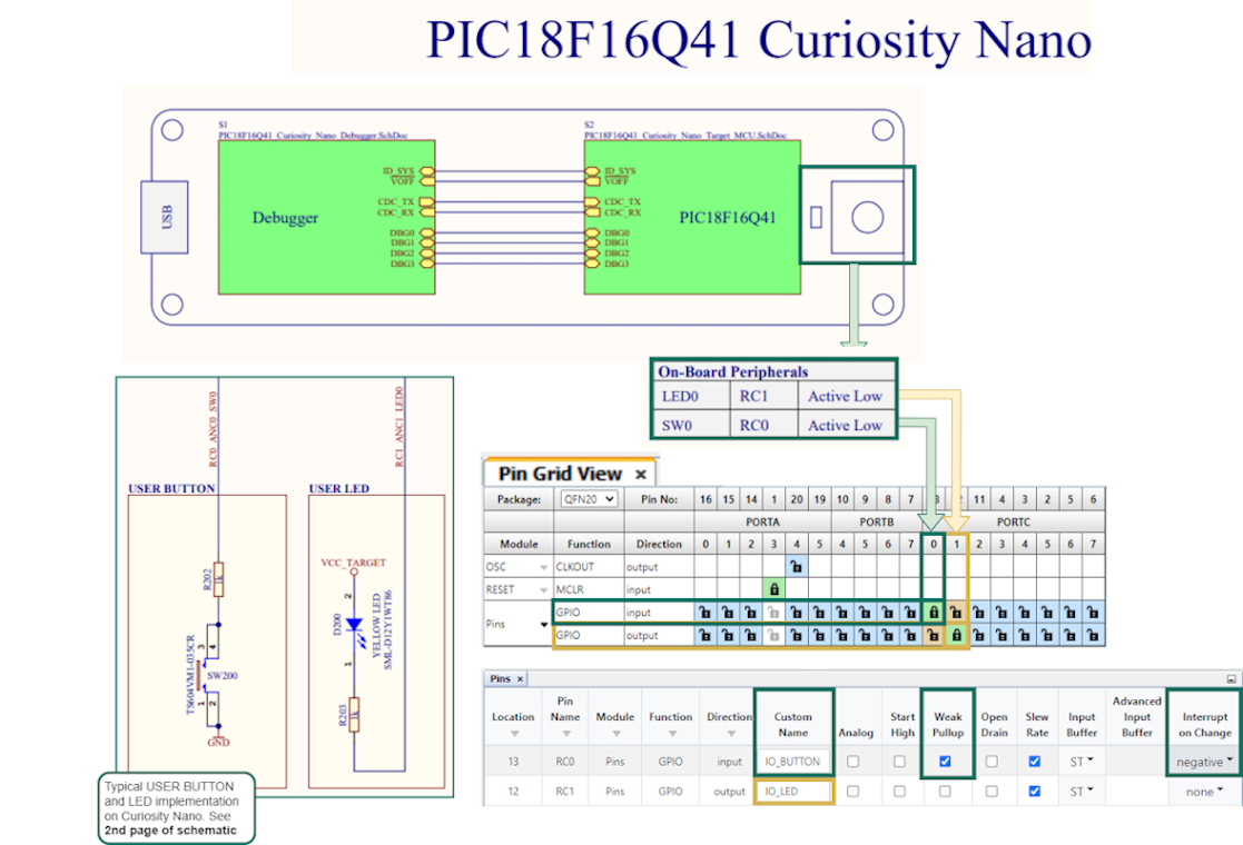
- Set the active low LED as output, rename to IO_LED.
- Set the active low BUTTON with no pull-up resistor as input, enable Weak Pull-up, set Interrupt-on-Change to Negative.
Debug GPIO pins are also provided on the Curiosity Nano via the Data Gateway Interface (DGI). Debug GPIO are particularly useful for a rough verification of application timing.
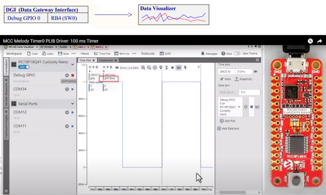
- Go to AVR TCA PLIB Driver, and PIC Timer0 PLIB Driver for a video on how to use the MCC Melody 100 ms Timer.
- If you are new to MPLAB® Data Visualizer, see Debug GPIO Hello World (Microchip University).