
3.5 How to Get Calibration Values
Microchip provides a Python script named "phycalibrationtool.py" to get optimal calibration values implied in the signal emission characterization, which could affect the ripple, amplitude and impedance algorithm detection used by PLC protocol implementations (Figure 3-7).
The script is intended to communicate with a physical PLC-based board running phy_tester_tool firmware.
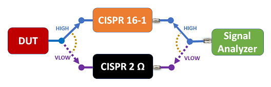
Along the test process, the PLC signal may be connected to different impedance loads; therefore, it is strongly recommended to uncouple the PLC signal from the mains power supply of the device under test (see the figure below).
- Initialization: Set the default equalization and gain calibration values used by the PLC PHY Calibration Tool.
- Equalization: The objective is to get a flatter frequency response of the signal on the band in use; for that, a maximum ripple must be defined below the customer limits. As a general rule, Microchip recommends a margin of 0.5-1 dB to handle the different impedance load of the equalization performed.
- Gain Calibration: The objective of gain calibration is to get the desired signal power in a range of variable gain for AUTO GAIN mode. An initial gain must be defined and the customer must decide minimum and maximum values for AUTO GAIN mode. The minimum value could have an impact on the performance of VLOW mode when emitting against high impedance if the system cannot emit low enough to maintain the signal on the PLC line. After modifying the gain values, it is strongly recommended to measure the ripple again to check if it was affected due to non-linearity when using a high level of power.
- Max RMS Level Process: It obtains the target RMS values for each transmission mode.
- Thresholds Process: The process calculates the threshold values to switch between transmission modes (HIGH to VLOW and opposite).

- GAIN_C: Present Gain Value: a valid value between the maximum and minimum set on calibration
- RMS_C: RMS Power Calculated
- RMS_C_C: RMS Power Calculated Corrected used for threshold comparing to change the TX mode
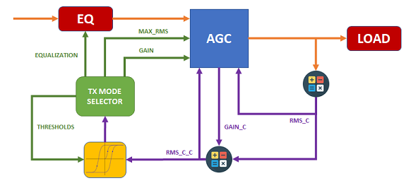
"Equalization" and "Gain Calibration" steps must be run iteratively and require the user to perform ripple and power measurements. On the other hand, the PHY Calibration Tool will automatically look for the best values on the "Max RMS Process" and "Thresholds Process" steps.