
2.2 3-CLCs Debouncing Solution
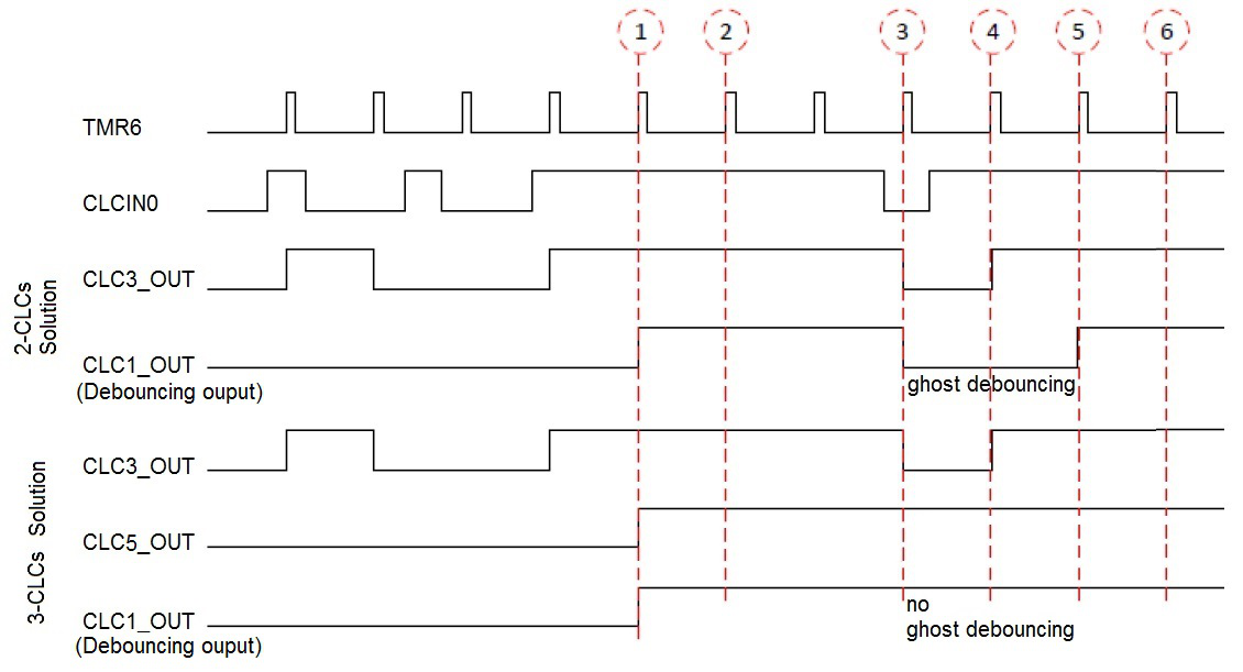
As discussed, the 2-CLCs solution is asymmetrical. The input signal needs to be logic HIGH for two clock cycles for the debouncing output to be HIGH and to be logic LOW for just one clock cycle for the debouncing output to be LOW. This is normally not a problem with asymmetrical debouncing time. However, when the input signal is holding HIGH while it has a LOW glitch which gets identified at the CLC clock edge, this will cause the output debouncing signal to go LOW for two clock cycles and ghost debouncing will occur. This is illustrated with the timing diagram of the 2-CLCs solution in Figure 2-3. The ghost debouncing scenario is illustrated at the marked 3rd clock edge where both CLCs outputs are LOW. This scenario has not occurred in experiments but the possibility exists. When this scenario happens, it is recommended to implement the 3-CLCs solution which avoids the occurrence of ghost debouncing.
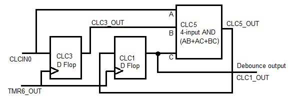
The logic diagram of the 3-CLCs solution is shown in Figure 2-4. The 1st CLC (CLC3) has the same input as before (see Figure 2-1). The 3rd CLC (CLC5) is chosen as a 4-input AND logic. The input signal and the first two CLC output signals are paired ANDed and then ORed together as
The output signal of the 3rd CLC provides the input signal to the 2nd CLC (CLC1). The 2nd CLC outputs the same debouncing signal as before. The 3rd CLC ensures no single LOW value on any of its three inputs will cause the debouncing output to go LOW. Figure 2-3 also shows the timing diagram of the 3-CLCs solution where the ghost debouncing does not exist anymore, which would occur in the 2-CLCs solution.
The PIC18F Q10 family with eight CLCs can only support debouncing on two buttons with the 3-CLCs solution. On the other hand, it can support four buttons with the 2-CLCs solution. Since the 2-CLCs solution is normally sufficient even for the extreme case as shown in Figure 2-2.c, the user can decide which solution to use or to use a combination of the two solutions based on their application requirement and also hardware resources.