
2.5 Preprogrammed Demo Software
Introduction
The PIC32WFI32E Curiosity Board comes with a Out-of-box demo application already programmed onto the PIC32MZ W1 device.
The demo has a web app and voice based interaction mode.
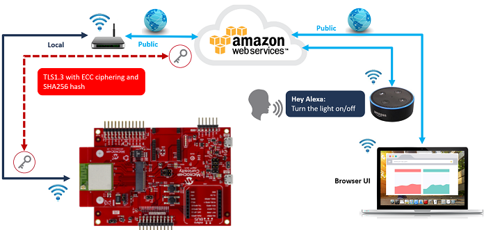
In the web-app based interaction mode, you will be able to visualize the data telemetry from the Curiosity board and interact with the Curiosity board using a web-browser based application.
In the voice control based interaction mode, you will be able to control the on-board user LED with voice commands using Amazon Alexa®.
All you will need is a board, a micro-USB cable, and a 2.4 GHz Wi-Fi connection. Follow this 30-second demo to set up Wi-Fi connection and start viewing live data...
Resources
Out-of-box Demo Landing Page with detailled instructions and Harmony 3 project source code
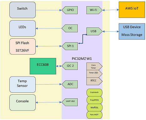
System architecture
File System media is hosted on external SPI Flash
File system is exposed to Host PC over USB Mass Storage Device
Trust&Go device certificate is used for tamper proof security and pre-provisioned for use with all major cloud vendors
The demo exposes the on-chip binary certificates through a “native filesystem” for easy access
Each device gets a cryptographically verifiable identity
Run the demo
With zero coding, follow the operations to get your device connected on the Internet.
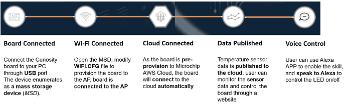
Setup board
Connect J202 jumper to VBUS-VIN.
Remove J301 jumpers.
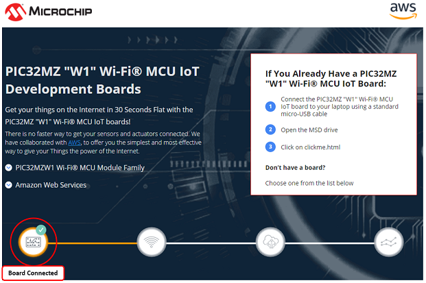
Plug In
Connect USB power connector (J204) of your board to your Windows, Mac, or Linux PC through a micro USB cable. Your PC will recognize the board as a removable storage drive.
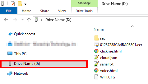
Link Up
The new drive contains several files.
Click on clickme.html to open your uniquely configured AWS cloud portal in a browser.
Scroll-down, enter your wireless network information on the page.
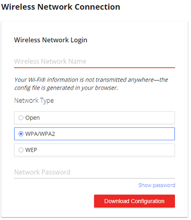
Click Download Configuration to download the Wi-Fi® configuration file WIFI.CFG and save the file in a dedicated folder on your hard drive (e.g. c:\pic32mzw1).
Drag and drop the new file WIFI.CFG to the root of the new drive and replace the existing file. Make sure the file is named exactly WIFI.CFG and the copy process is completed.
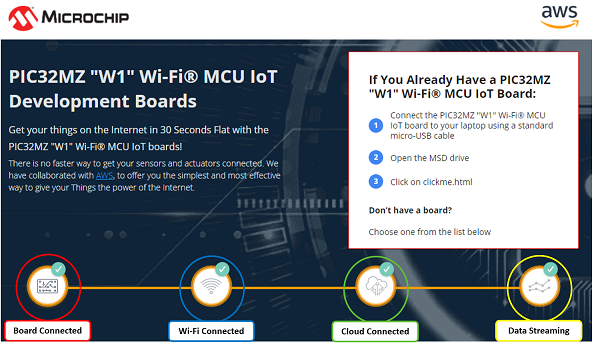
Reboot the board by pressing MCLR button.
Your board will automatically connect to the network.
Check out the FAQ in you are having trouble to connect.
Dive In
Once your board is connected, you'll immediately be able to dive into your temperature data through Microchip’s AWS cloud sandbox.
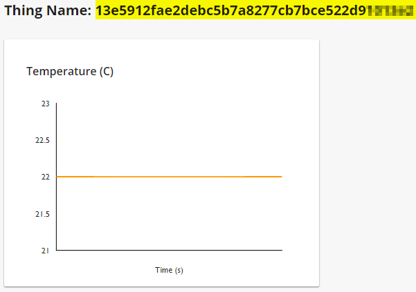
On top of the temperature graph, copy the unique Thing Name in the clipboard.
Click
button
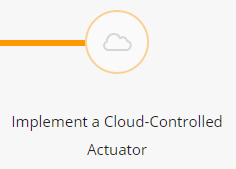
To control the on-board LED from the cloud, select "Implement a Cloud-Controlled Actuator"
Click
button
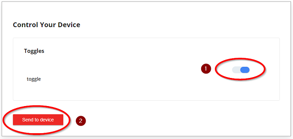
Select an LED state
Click on "Send to Device" to trigger a cloud message to control the on-board Green LED.
Microchip’s sandbox is for demonstration purposes. Learn here how to connect the demo to your own AWS cloud instance.
Use your voice
Go back to the content of the new drive mounted

Click on voice.html
Simply create an account to Microchip front-end web page then log-in
Register your device:
your unique Thing Name previously copied to clipboard
a friendly name such as "pic32 light"
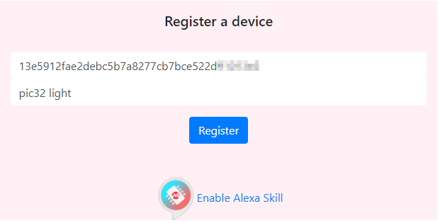
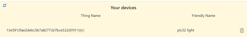
After claiming your new device, it will appear on the left window
Install and open the Amazon Alexa® app on your smartphone/tablet
Enable the Microchip IoT Skill
Type the same user and password you have used to create an account within Microchip Cloud over voice.html
The app will discover your device and add it within your device list
Control the board through Amazon Alexa® by using the friendly name
E.g. Alexa, turn on "pic32 light"
E.g. Alexa, turn off "pic32 light"
Customize the demo
Clone/download the latest source code of the demo
Add Button Status
The user switch (SW1) will be used to simulate another sensor.
Go to the main web-app page: https://pic-iot.com/pic32mzw1/aws/
In "What's next?" section, select "Add more sensor data"
Click
buttonThe web app will be expose the step-by-step instructions
Using MPLAB X IDE:
open/modify the project accordingly
compile and program the code on your board
Link up again your device to the cloud
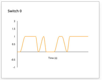
Observe the button status on the web-app
Add your own sensor
Good practice to use MCC to change any configuration settings of components or services.
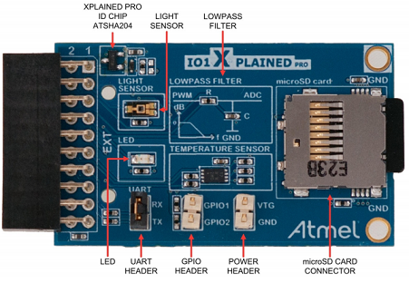
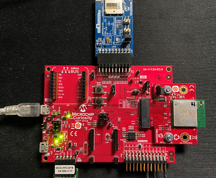
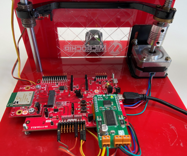
For the purpose of this demo, let's hack the demo by adding the Light Sensor from IO1 Xplained Pro Extension Kit and connect this board to Xpro header (J203) of the WFI32 Curiosity Board.
That will perform the following connection:
| IO1 XPRO Extension Header | WFI32 Curiosity Board XPRO Header |
|---|---|
| Pin 2 - GND | Pin 2 - GND |
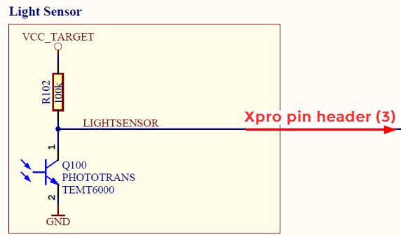
| Pin 3 - LIGHTSENSOR OUT | Pin 3 - TMS/AN6/CVD6/CVDR6/CVDT1/RPB6 |
| Pin 20 - VCC | Pin 20 - VCC |
The IO1 XPRO contains the light sensor TEMT6000 from Vishay. The light sensor is a single-ended analog output. When light is being blocked, the pull-up resistor will pull the signal voltage to 3.3V. When light is absorbed by the phototransistor, that will cause a current flow and pulling the signal voltage down to 0.0 V.
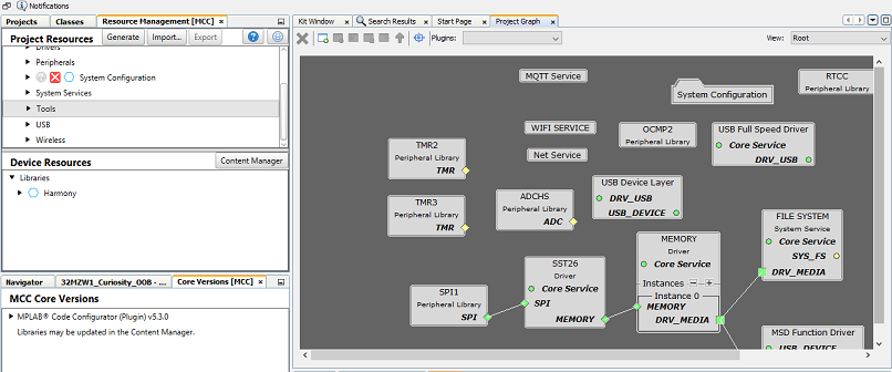
Open the latest code of the OoB demo project
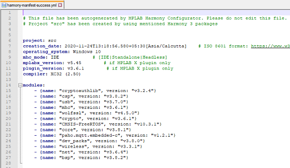
The demo project has been written with certain versions of Harmony 3 components. The version of the Harmony 3 components used in this project are listed in the file harmony-manifest-success.yml located in the folder src/firmware/src/config/pic32mz_w1_curiosity.
Open MCC
From Plugins select ADCHS Configuration
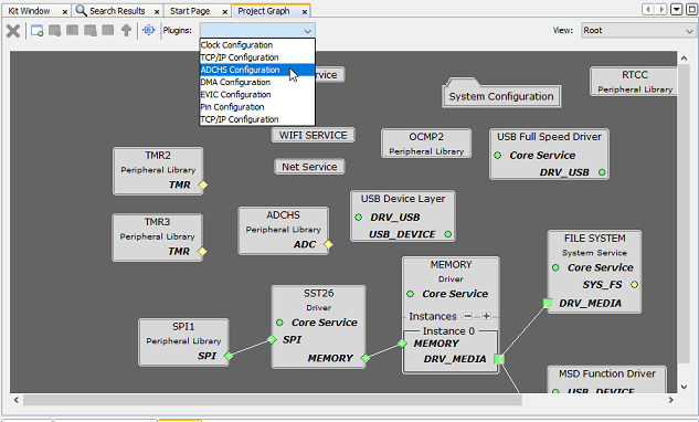
Select ADC7 Enabled
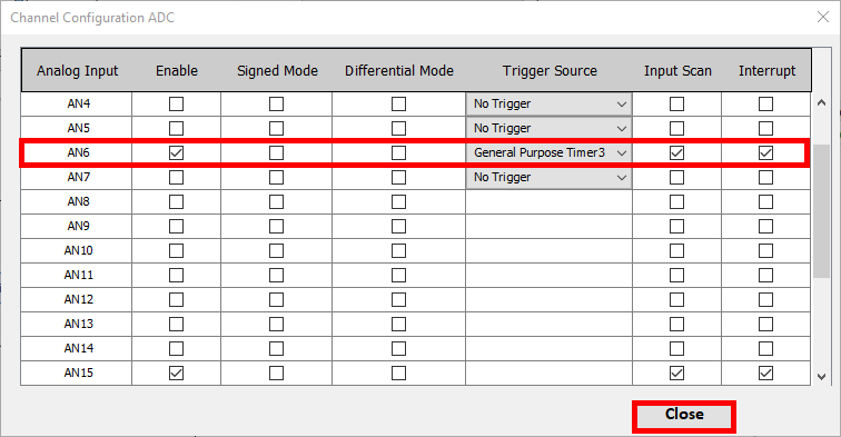
Click Channel Selection
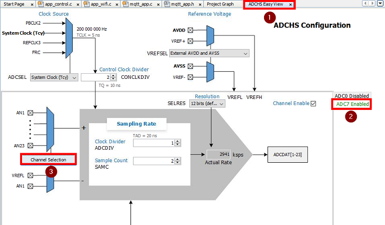
Enable AN6, trigger source as General Purpose Timer3 with Input Scan and Interrupt and close the window.
Increase the ADC acquistion time by
Changing ADC Clock Divider to 64 to obtain TAD = 640 ns
Changing ADC Sample Count to 20
Both changes will result to lower acquisition rate
The ADCHS block of the PIC32MZW1 can operates very fast. However in the current hardware, there are no external buffer circuit in order to reduce the impedance between the sensors and the ADC inputs. Thus acquisition time must be just long enough to charge the sample capacitor and conversion time must be long enough for sucessive approximation to complete while being as short as possible to prevent charge leakage loss.
For more info, checkout: datasheet, 12-bit SAR ADC Reference Manual, or this article for insights.
Click Generate Code
Apply the requested modifications
Files to modify in order to adapt the demo:
app_control.c
app_control.c
app_control.h
mqtt_app.c
mqtt_app.h
Open header file app_control.h
Modify the existing APP_CTRL_ADC_DATA structure by adding three new variables related to light sensor (lightReady, lightCount and light):
  typedef struct {
      bool dataReady;
      uint16_t adcCount;
      float temp;
      bool lightReady ;
      uint16_t lightCount ;
      float light ;
  } APP_CTRL_ADC_DATA;
Open source file app_control.c
In APP_CONTROL_Initialize(), reset the values of the new items lightCount and lux:
  /*init ADC data*/
  app_controlData.adcData.dataReady = false;
  app_controlData.adcData.adcCount = 0;
  app_controlData.adcData.temp = 0;
  app_controlData.adcData.lightReady = false ;
  app_controlData.adcData.lightCount = 0 ;
  app_controlData.adcData.light = 0 ;
Modify the ADC_ResultHandler() as below to the handle and get the ADC results of CH6 and CH15.
  void ADC_ResultHandler(ADCHS_CHANNEL_NUM channel, uintptr_t context) {
  switch(channel)
  {
      case ADCHS_CH15:
          app_controlData.adcData.adcCount = ADCHS_ChannelResultGet(ADCHS_CH15);
          app_controlData.adcData.dataReady = true;
          break ;
      case ADCHS_CH6:
          app_controlData.adcData.lightCount = ADCHS_ChannelResultGet(ADCHS_CH6) ;
          app_controlData.adcData.lightReady = true ;
          break ;
      default:
          break ;
  }
  }
Scroll-down in app_control.c
In APP_CONTROL_Tasks() function, register the callback functions to be called at the end of conversion on CH15 and CH6 in APP_CONTROL_STATE_INIT switch case.
  void APP_CONTROL_Tasks(void) {
  WDT_Clear();
  switch (app_controlData.state) {
  case APP_CONTROL_STATE_INIT:
  {
      // Registers the ADC callback function for channel CH15 and CH6
      ADCHS_CallbackRegister(ADCHS_CH15, ADC_ResultHandler, (uintptr_t)NULL);
      ADCHS_CallbackRegister(ADCHS_CH6, ADC_ResultHandler, (uintptr_t)NULL);

      TMR3_Start(); /*TMR3 is used for ADC trigger*/

      RTCC_CallbackRegister(RTCC_Callback, (uintptr_t) NULL);
      setup_rtcc();
      indicator_on();
      app_controlData.state = APP_CONTROL_STATE_MONITOR_CONNECTION;
      break;
  }
Continue scrolling-down in APP_CONTROL_Tasks() function and modify the switch-case APP_CONTROL_STATE_ADC_READ as below. Just add the portion of code related to light sensor below the temperature sensor section.
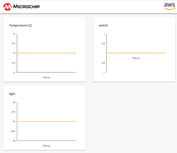
  case APP_CONTROL_STATE_ADC_READ:
  {
      /*Average over APP_CTRL_ADC_AVG_COUNT ADC samples*/
      // Temperature sensor
      static uint32_t adcCountAccumulate = 0;
      static uint16_t adcAccumulateNum = 0;
      if (app_controlData.adcData.dataReady) {
          if (adcAccumulateNum <= APP_CTRL_ADC_AVG_COUNT) {
              adcCountAccumulate += app_controlData.adcData.adcCount;
              adcAccumulateNum++;
          } else {
              adcCountAccumulate = adcCountAccumulate / APP_CTRL_ADC_AVG_COUNT;
              float input_voltage = (float) adcCountAccumulate * APP_CTRL_ADC_VREF / APP_CTRL_ADC_MAX_COUNT;
              float temp = ((input_voltage - .7) / .1)*10;
              app_controlData.adcData.temp = temp;
              /*For the next averaging cycle*/
              adcAccumulateNum = 0;
              adcCountAccumulate = 0;
              //SYS_CONSOLE_PRINT("Temp=%0.1f\r\n",app_controlData.adcData.temp);
          }
          app_controlData.adcData.dataReady = false;
      }
      // Light sensor
      static uint32_t lightCountAccumulate = 0 ;
      static uint16_t lightAccumulateNum = 0 ;
      if (app_controlData.adcData.lightReady) {
          if (lightAccumulateNum <= APP_CTRL_ADC_AVG_COUNT) {
              lightCountAccumulate += app_controlData.adcData.lightCount ;
              lightAccumulateNum++ ;
          } else {
              lightCountAccumulate = lightCountAccumulate / APP_CTRL_ADC_AVG_COUNT ;
              app_controlData.adcData.light = 100 - (lightCountAccumulate * 100 / APP_CTRL_ADC_MAX_COUNT) ;
              /*For the next averaging cycle*/
              lightAccumulateNum = 0 ;
              lightCountAccumulate = 0 ;
              //SYS_CONSOLE_PRINT("Light=%0.1f\r\n",app_controlData.adcData.light);
          }
          app_controlData.adcData.lightReady = false ;
      }
      app_controlData.state = APP_CONTROL_STATE_RTCC_READ;
      break;
  }
Open header file mqtt_app.h add a new JSON template called MQTT_APP_TELEMETRY_MSG_GRAD2_TEMPLATE and include light sensor value along with existing temperature and switch status
#define MQTT_APP_TELEMETRY_MSG_GRAD2_TEMPLATE "{\"Temperature (C)\": %d,\"switch\":%d,\"light\":%d}"Open source file mqtt_app.c and search for publishMessage() function
Comment out the existing telemetry message lines and add the new graduation step: sprintf(message, MQTT_APP_TELEMETRY_MSG_GRAD2_TEMPLATE, (int) app_controlData.adcData.temp,app_controlData.switchData.switchStatus, (int) app_controlData.adcData.light);
  if (!mqtt_appData.shadowUpdate) { /*if a shadow update is requested, do it in this round*/
          snprintf(pubTopic, SYS_MQTT_TOPIC_NAME_MAX_LEN, "%s/sensors", app_controlData.mqttCtrl.clientId);
          //sprintf(message, MQTT_APP_TELEMETRY_MSG_TEMPLATE, (int) app_controlData.adcData.temp);
          /*Graduation step to include an additional sensor data. Comment out the above line and uncomment the one below.*/
          //sprintf(message, MQTT_APP_TELEMETRY_MSG_GRAD_TEMPLATE, (int) app_controlData.adcData.temp,app_controlData.switchData.switchStatus);
          sprintf(message, MQTT_APP_TELEMETRY_MSG_GRAD2_TEMPLATE, (int) app_controlData.adcData.temp,app_controlData.switchData.switchStatus, (int) app_controlData.adcData.light);
      }
Clean and Build project
Run project
Perform the steps detailled above to Run the demo
With the above modifications, you should be able to observe the temperature sensor value (ADCHS_CH15), the status of the user switch (SW1) and the light sensor (ADCHS_CH6) on the front-end web page.
Smart Garage door demo
Based on the OoB MPLAB Harmony project v2.0.2 and the WFI32E Curiosity board the Garage door demo has been built to showcase another possibility of the WFI32E device.
Voice commands using Amazon Alexa or the web-app page can be used to control the garage door through Amazon AWS cloud.
Watch the video and see how to voice control a garage door using a secure cloud connectivity with WFI32E Curiosity board.
BoM
This demo is using the following components:
WFI32E Curiosity board
42HS02 stepping motors with 4 leads
2x subminiature basic switches
5VDC to power supply the WFI32E Curiosity board
15VDC 3A power supply for the motor
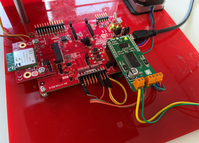
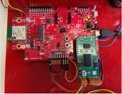
Hardware Setup
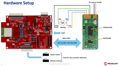
The PIC32MZ W1 communicates to the 8-bit I/O expander MCP23S08 over the SPI-lines and it allows the control lines of the MTS62C19A motor driver IC. By changing states of the MTS62C19A's control pins, it is possible to drive the stepper motor.
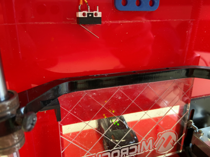
Two basic switches are used to detect the garage door position.
Software
To use voice command, make sure to register and claim the device using voice.html
Clone/download this repo to find the source code of this demo
The Harmony 3 project of the Garage Door Demo is based on OoB project version 2.0.2 and it is tested with the following software components:
MHC v3.8.2
MPLAB X v6.00
Plugin v3.6.4
Compiler XC32 3.01
cryptoauthlib v20211006
csp v3.10.0
usb v3.8.1
wolfssl v4.7.0
crypto v3.7.5
CMSIS-FreeRTOS v10.3.1
core v3.10.0
wireless_wifi v3.6.1
paho.mqtt.embedded-c v1.2.3
dev_packs v3.10.0
littlefs
wireless_system_pic32mzw1_wfi32e01 v3.6.1
net v3.7.4
The manifest file src/firmware/src/config/pic32mz_w1_curiosity/harmony-manifest-success.yml has been loaded using Harmony Content Manager to get same package configuration as the original project.
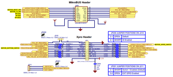
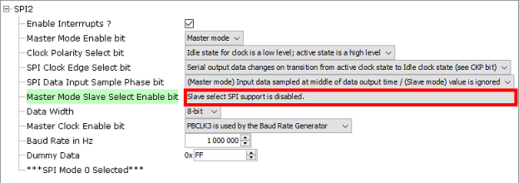
In MHC, SPI2 component is added to allow PIC32MZ W1 device driving the stepper motor mikroE board. Chip select pin is driven by software.
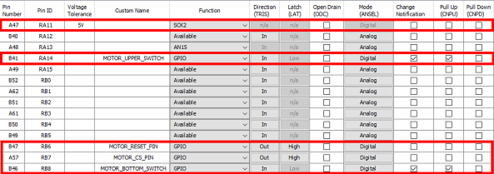
The pins have been configured to match the hardware connection.
The application app_motor has been added in addition to the existing 5 application files to take care of the tasks related to the motor.
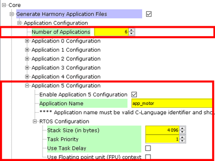
The FreeRTOS task APP_MOTOR_Tasks is managing the stepper motor by starting the motor when desired state is triggered via MQTT message and stopping the motor by de-energizing the coil when the garage door has reached the position of one of the switches.