
3.1.2 TrustZone Getting Started on PIC32CK SG01 Curiosity Ultra Development Board using Harmony Drivers
Description
This application demonstrates the TrustZone feature on the PIC32CK SG01 microcontroller (MCU). The application has two projects pertaining to Secure and Non-Secure modes of PIC32CK SG01 that work together on the same MCU and offer security isolation between the trusted and the non-trusted resources in the device.
- In Non-secure mode, the application reads the current room temperature (raw data) from the I/O1 Xplained Pro Extension Kit sensor every 1 second. The Secure mode application processes this raw data, converting it into readable temperature values. When requested by the Non-secure mode application, the Secure mode application sends the converted temperature values through Non-Secure Callable (NSC), and the temperature values are displayed on the serial console.
- Additionally, the Non-secure mode application stores the temperature readings in the EEPROM. When a key is pressed on the serial console, the application can display the last five stored temperature values from the EEPROM on the console. An LED (LED0) toggles each time the temperature is displayed on the serial console.
Modules/Technology Used
-
Peripheral Modules
- Non-secure TCC0
- Non-secure DMAC
- Secure PORT Pin (LED0)
-
Driver Modules
- Non-secure USART
- Non-secure I2C
-
System Services
- Time
-
Core
The MCC Harmony project graph with all the components would look like this: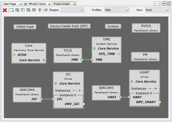
Hardware Used
Software/Tools Used
Refer Project Manifest present in harmony-manifest-success.yml under the project folder firmware/src/config/pic32ck_sg01_cult
- Refer the Release Notes to know the MPLAB X IDE and MCC Plugin version.
- Any Serial Terminal application like Tera Term/PuTTY terminal application.
Because Microchip regularly update tools, occasionally issue(s) could be discovered while using the newer versions of the tools. If the project doesn’t seem to work and version incompatibility is suspected, It is recommended to double-check and use the same versions that the project was tested with. To download original version of MPLAB Harmony v3 packages, refer to document How to Use the MPLAB Harmony v3 Project Manifest Feature
Hardware Setup
- The PIC32CK SG01 Curiosity Ultra Development Board allows the Embedded Debugger (PKoB4) to be used for debugging.
- Connect the PIC32CK SG01 Curiosity Ultra Development Board to the host PC using a Type-A male to micro-B USB cable. Plug the cable into the Micro-B USB (Debug USB) port on the Development Board.
- To test the
functionality, connect the I/O1 Xplained Pro Extension
Kit to the extension header EXT1 (J500) on the PIC32CK SG01
Curiosity Ultra Development Board.

Programming hex file
The pre-built hex file can be programmed by following the below steps.
Steps to program the hex file- Open MPLAB X IDE
- Close all existing projects in IDE, if any project is opened.
- Go to File -> Import -> Hex/ELF File
- In the "Import Image File" window, Step 1 - Create Prebuilt Project, Click the "Browse" button to select the prebuilt hex file.
- Select Device has "PIC32CK2051SG01144"
- Ensure the proper tool is selected under "Hardware Tool"
- Click on Next button
- In the "Import Image File" window, Step 2 - Select Project Name and Folder, select appropriate project name and folder
- Click on Finish button
- In MPLAB X IDE, click on "Make and Program Device" Button. The device gets programmed in sometime
- Follow the steps in "Running the Demo" section below
Programming/Debugging Application Project
- Open the project (pic32ck_sg01_cult_getting_started_drv/firmware/getting_started_drv_pic32ck_sg01_cultgroup) in MPLAB X IDE
- Right click on "getting_started_drv_pic32ck_sg01_cultgroup" file and go to Open Required projects > Open All Projects.
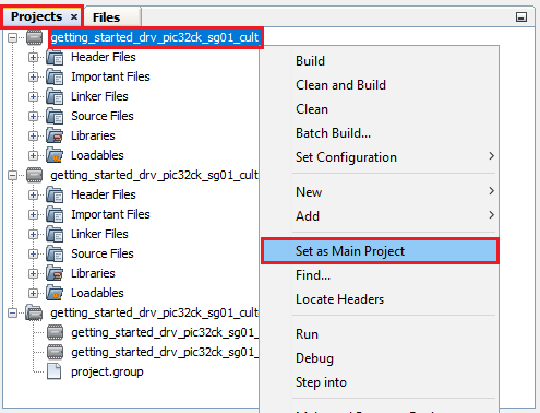
- Then right click on the
Non-secure project (getting_started_drv_pic32ck_sg01_cult
project) and click Set as Main Project.
- Ensure "PIC32CK SG01 Curiosity Ultra" is selected as hardware tool to program/debug the application
- Build the code and program the device by clicking on the "make and program" button in MPLAB X IDE tool bar
- Follow the steps in "Running the Demo" section below
Running the Demo
- Open the Tera Term/PuTTY terminal application on your PC (from the Windows® Start menu by pressing the Start button)
- Set the baud rate to 115200
- An LED0 on the PIC32CK
SG01 Curiosity Ultra Development Board is toggles continuously using the
System Timer as shown in the below figure.

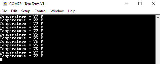
- The LED0 should be
blinking and the temperature values (in °F) being displayed on the
terminal every 1 second, as shown below.
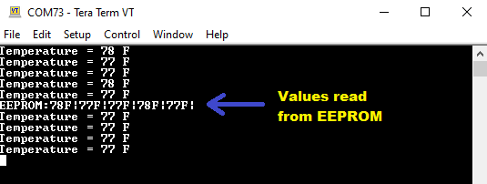
- Press any character on
the terminal to display the last five values written to the EEPROM.
- Vary the temperature by
placing your finger on the temperature sensor on the I/O1 Xplained Pro
Extension Kit (for a few seconds).

Comments
- Dual Developer Application
Development Use Case with TrustZone on SAM L11 Using MPLAB Harmony
v3 (DS90003306)
-
Note: Though this technical brief is on SAM L11 MCUs, the TrustZone concepts it describes also applies to PIC32CK SG01 MCUs.
-
- This application demo
builds and works out of box by following the instructions above in
"Running the Demo" section. If you need to enhance/customize this
application demo, you need to use the MPLAB Harmony v3 Software
framework. Refer links below to setup and build your applications using
MPLAB Harmony.
- How to Setup MPLAB Harmony v3 Software Development Framework (DS90003232)
- How to Build an Application by Adding a New PLIB, Driver, or Middleware to an Existing MPLAB Harmony v3 Project (DS90003253)
- Video - How to Set up the Tools Required to Get Started with MPLAB® Harmony v3 and MCC
- Create a new MPLAB Harmony v3 project using MCC
- Update and Configure an Existing MHC-based MPLAB Harmony v3 Project to MCC-based Project