
3.1.1 TrustZone Getting Started on PIC32CK SG01 Curiosity Ultra Development Board
Description
This application demonstrates the TrustZone feature on the PIC32CK SG01 microcontroller (MCU). The application has two projects pertaining to Secure and Non-Secure modes of PIC32CK SG01 that work together on the same MCU and offers security isolation between the trusted and the non-trusted resources in the device.
The application includes Basic and Extended functionalities.
- Basic Application
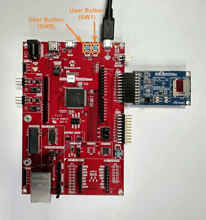
- The Secure mode application toggles an LED (LED0 toggles when the switch SW0 is pressed) on a timeout basis and the periodicity of the timeout will change from 500 milliseconds to one second, two seconds, four seconds, and back to 500 milliseconds every time the switch SW0 is pressed on the PIC32CK SG01 Curiosity Ultra Development Board.
- The Non-secure application requests the Secure mode application, reads the LED toggling rate and prints on the serial terminal. The LED toggling rate data is transferred to the Non-secure mode application when it requests to Secure application through Non-Secure Callables (NSC).
- Extended Application
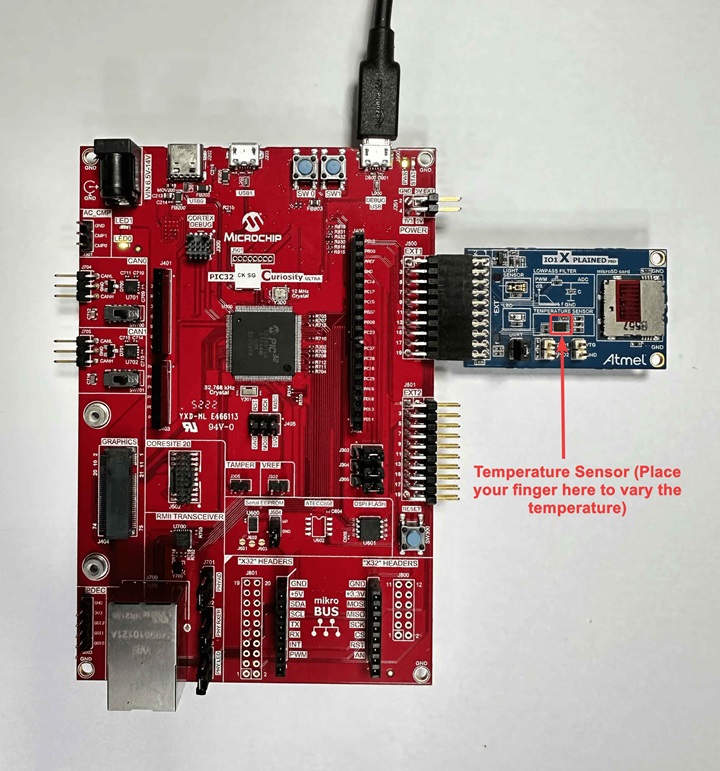
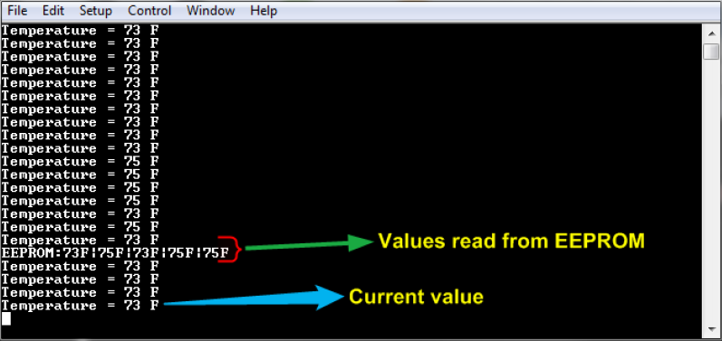
- The Secure mode application reads the current room temperature from the temperature sensor on the I/O1 Xplained Pro Extension Kit every 500 milliseconds. Further, the application writes the temperature readings to EEPROM and reads when a request is received from the Non-secure mode application. Also, a green LED (LED0) is toggled every time the temperature display request is received from the Non-secure mode application. The periodicity of the temperature values reading can be changed to 1 second, 2 seconds, 4 seconds, and back to 500 milliseconds whenever the user presses the switch SW0 on the PIC32CK SG01 Curiosity Ultra Development Board. The temperature readings are transferred to the Non-secure mode application when it requests to Secure application through Non-Secure Callables (NSC).
- The Non-secure mode application requests the temperature values from the secure mode application and prints them on a serial console once it receives from the Secure mode application. Further, when it gets a request from the user (in the form of a key press on the serial console), it will request the Secure mode application to retrieve the last five stored temperature values in the EEPROM. The Non-secure application prints the last five stored temperature values on the console. Also, a red LED (LED1) is toggled every time the temperature values are read from EEPROM.
Modules/Technology Used
- Peripheral Modules
- Secure PORT Pins (All pins by default are secure)
- Secure I2C
- Secure RTC
- Secure EIC
- Non-secure USART
- Non-secure DMAC
- Non-secure PORT Pins (USART Pins only)
Hardware Used
Software/Tools Used
This project has been verified to work with the following versions of software tools:
Refer Project Manifest for Secure and NonSecure projects presents in harmony-manifest-success.yml under the project folder {firmware_secure or firmware}/src/config/default
- Refer the Release Notes to know the MPLAB X IDE and MCC Plugin version.
- Any Serial Terminal application such as Tera Term terminal application.
Because Microchip regularly updates tools, occasionally issue(s) could be discovered while using the newer versions of the tools. If the project does not seem to work and version incompatibility is suspected, it is recommended to double-check and use the same versions that the project was tested with. To download original version of MPLAB Harmony v3 packages, refer to document How to Use the MPLAB Harmony v3 Project Manifest Feature (DS90003305).
Hardware Setup 1
- The PIC32CK SG01 Curiosity Ultra Development Board allows the Embedded Debugger (PKoB4) to be used for debugging.
- Connect the Type-A male to Micro-B USB
cable to Micro-B DEBUG USB port (J900) to power and debug the PIC32CK SG01 Curiosity
Ultra Development Board.
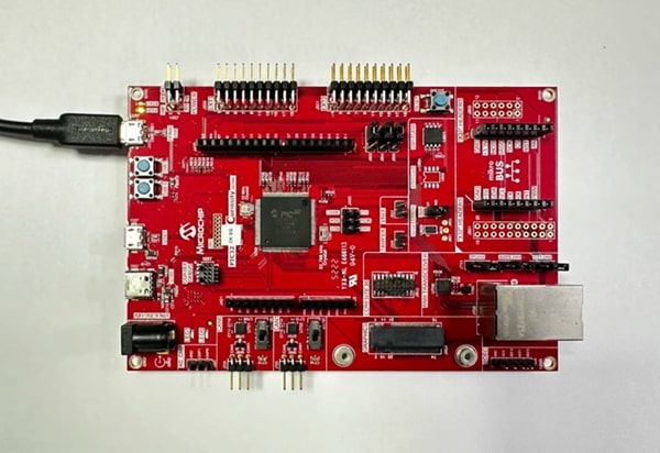
- The PIC32CK SG01 Curiosity Ultra Development Board allows the Embedded Debugger (PKoB4) to be used for debugging. Connect the Type-A male to micro-B USB cable to the micro-B DEBUG USB port to power and debug the PIC32CK SG01 Curiosity Ultra Development Board.
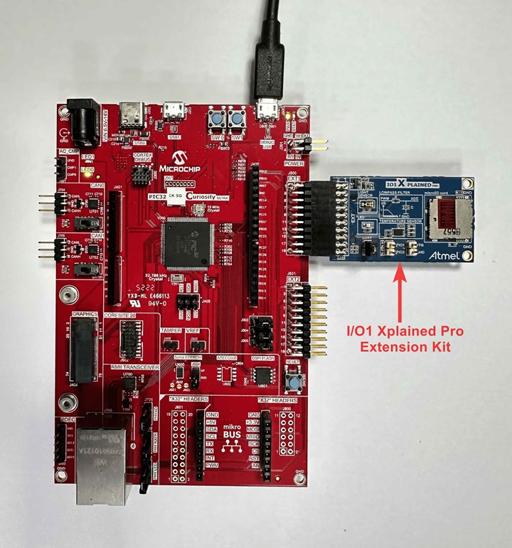
Hardware Setup 2
- The PIC32CK SG01 Curiosity Ultra Development Board allows the Embedded Debugger (PKoB4) to be used for debugging.
- Connect the Type-A male to Micro-B USB cable to Micro-B DEBUG USB port (J900) to power and debug the PIC32CK SG01 Curiosity Ultra Development Board.
- To test the extended functionality, connect the I/O1 Xplained Pro Extension Kit to the extension header EXT1 (J500) on the PIC32CK SG01 Curiosity Ultra Development Board.
TrustZone Application Development Use Cases
- There are two use cases:
- Single Developer (This application demonstrates a single developer use case)
- Dual Developer
- Single Developer
- A single developer develops both Secure and Non-Secure applications.
- The following steps are automatically
taken care of by the MCC.
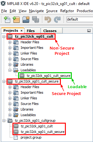
- MCC generates both Secure and
Non-Secure projects and sets the Secure project as a loadable project to the
Non-Secure project.
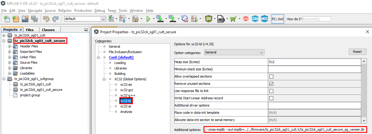
- Configure the Secure project to
generate the veneer library in the Non-Secure project path
(firmware/tz_pic32ck_sg01_cult.X/tz_pic32ck_sg01_cult_secure_sg_veneer.lib).
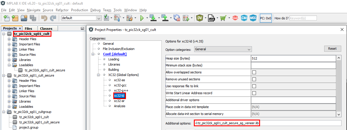
- Configure the Non-Secure project
to link the veneer library.
- MCC generates both Secure and
Non-Secure projects and sets the Secure project as a loadable project to the
Non-Secure project.
- Dual Developer
- The dual developer use case involves two developers.
- Initially, Developer A is responsible
for developing the Secure application; then, Developer B is responsible for developing
the Non-Secure application.
- Refer Comments for more details on the Dual Developer Application Development Use Case.
Programming Methods
Method 1: Steps for Programming prebuilt hex file
- The TrustZone project will have Secure and Non-Secure pre-built hex files.
- Program Secure hex file first followed by the Non-Secure hex file.
- The following are the steps to program these hex files.
- Extract the pic32ck_sg01_cult_tz_getting_started project.
- Open MPLAB X IDE.
- Close all existing projects in IDE, if any project is opened.
- Go to File -> Import -> Hex/ELF File.
- In the Import Image File
window,
- Create Prebuilt Project,
- Click the Browse button to select the prebuilt tz_pic32ck_sg01_cult_secure.X.production.hex file from project path pic32ck_sg01_cult_tz_getting_started/hex.
- Select Device as PIC32CK2051SG01144.
- Ensure PIC32CK SG01 Curiosity Ultra is selected under Hardware Tool and click Next button.
- Select Project Name and Folder,
- Select appropriate project name and folder and click Finish button.
- Create Prebuilt Project,
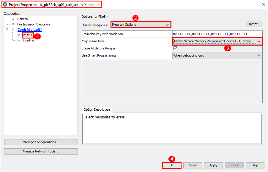
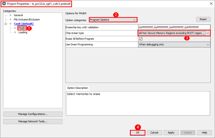
- Go to project properties and set
Program Options under PKoB4 categories to erase and program only Secure memory
region.
- In MPLAB X IDE, click on Make and Program Device button to program the device.
- Go to File -> Import -> Hex/ELF File.
- In the Import Image File
window,
- Create Prebuilt Project,
- Click the Browse button to select the prebuilt tz_pic32ck_sg01_cult.X.production.hex file from project path pic32ck_sg01_cult_tz_getting_started/hex.
- Select Device as PIC32CK2051SG01144.
- Ensure PIC32CK SG01 Curiosity Ultra is selected under Hardware Tool and click Next button.
- Select Project Name and Folder,
- Select appropriate project name and folder and click Finish button.
- Create Prebuilt Project,
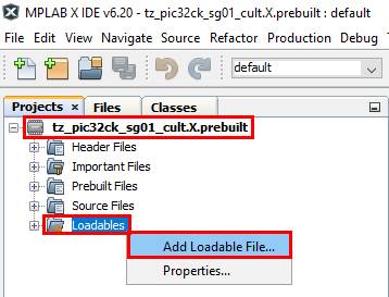
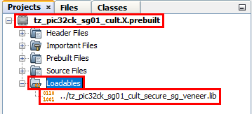
- In the
tz_pic32ck_sg01_cult.X.prebuilt project, right click on Loadables folder
and click on Add Loadable File to add Secure Gateway veneer library as shown
below.
- Select
tz_pic32ck_sg01_cult_secure_sg_veneer.lib veneer library.
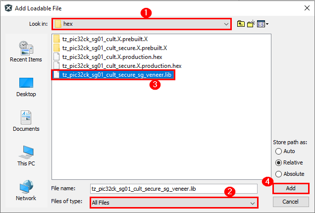
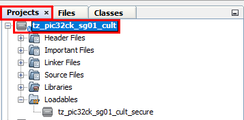
- Expand Loadables folder to confirm that
the veneer library is added to the Non-Secure project.
- Go to project properties and set
Program Options under PKoB4 categories to erase and program only Non-Secure
memory region.
- In MPLAB X IDE, click on Make and Program Device button to program the device.
- Follow the steps in Running the Demo section.
Method 2: Programming/Debugging Application Project
- The Trustzone project can be opened in
two ways:
- Procedure 1
- Open MPLAB X IDE.
- Close all existing projects in IDE (if any project is opened).
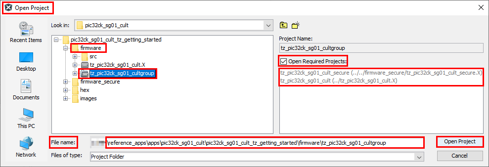
- Go to File -> Open Project.
- Go to reference_apps
repo path and navigate to following path
<reference_apps_path>/apps/pic32ck_sg01_cult/pic32ck_sg01_cult_tz_getting_started. - Select
tz_pic32ck_sg01_cultgroup in firmware folder (Non-Secure project
folder), and select enable Open Required Projects (this option opens both
Secure and Non-secure projects) and click on Open Project button.
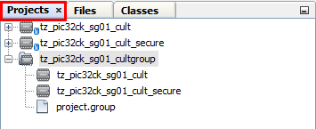
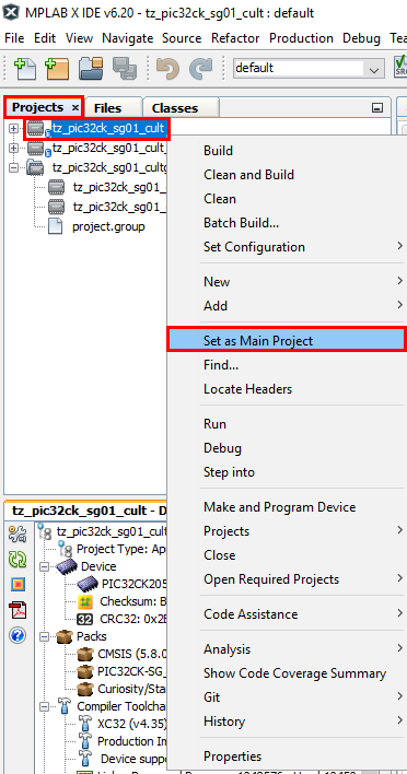
- Once the project opens, set the
tz_pic32ck_sg01_cult project (Non-Secure Project) as Main Project by
right clicking on the project.
- Procedure 2:
- Open MPLAB X IDE.
- Close all existing projects in IDE (if any project is opened).
- Open the project
(../pic32ck_sg01_cult_tz_getting_started/firmware/tz_pic32ck_sg01_cult.X) in
MPLAB X IDE.
- Ensure PIC32CK SG01 Curiosity Ultra is selected as hardware tool to program/debug the application.
- Build the code and program the device by clicking on the Make and Program Device button in MPLAB X IDE tool bar.
- Follow the steps in Running the Demo section.
-
Note:
- Windows OS has a maximum path length of 260 characters and a command-line limitation for Windows OS of 8191 characters.
- The TrustZone based project come with long path name, hence the project build may fail due to exceeding Windows maximum path length.
- Workaround: Move the project folder to C:/ drive to reduce the project path length then open in MPLAB X IDE to build the project.
- Procedure 1
Running the Demo
- Basic Functionality
- Perform Hardware Setup 1 steps mentioned above, if not done already.
- Open the Tera Term terminal application on the PC (from the Windows® Start menu by pressing the Start button).
- Set the baud rate to 115200.
- Reset or power cycle the device. LED0 toggles for every 500 milliseconds during power cycle.
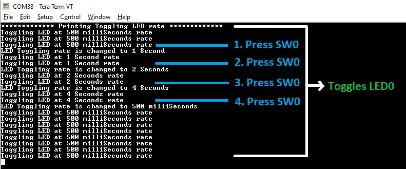
- An LED (LED0) on the PIC32CK SG01 Curiosity Ultra Development Board toggles on every timeout basis and the default periodicity of the timeout is 500 milliseconds.
- And also, the LED toggling rate is displayed on the serial terminal.
- Press the switch SW0 on the PIC32CK SG01 Curiosity Ultra Development Board to change the periodicity of the timeout to one second.
- Every subsequent pressing of the switch SW0 on the PIC32CK SG01 Curiosity Ultra Development Board changes the periodicity of the timeout to 2 seconds, 4 seconds, 500 milliseconds, and back to 1 second in cyclic order.
- See the following figure for the
output.
- Extended Functionality using I/O1 Xplained Pro Extension Kit
- Perform Hardware Setup 2 steps mentioned above, if not done already.
- Open the Tera Term terminal application on the PC (from the Windows® Start menu by pressing the Start button).
- Change the baud rate to 115200.
- Press SW1 to start running the extended functionality.
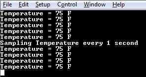
- The temperature values (in °F) are
displayed on the terminal every 500 milliseconds, as shown below.
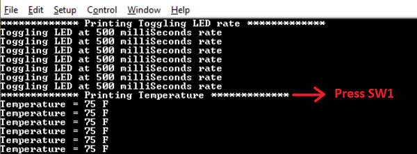
- Also, notice the LED0 blinking at 500 millisecond rate.
- The user may vary the temperature
by placing the finger on the temperature sensor (for a few seconds).
- Press the switch SW0 on PIC32CK
SG01 Curiosity Ultra Development Board to change the default sampling rate to 1
second.
- Every subsequent pressing of switch
SW0 on PIC32CK SG01 Curiosity Ultra Development Board changes the default sampling
rate to 2 seconds, 4 seconds, and 500 ms and back to 1 second in cyclic order as
shown below.
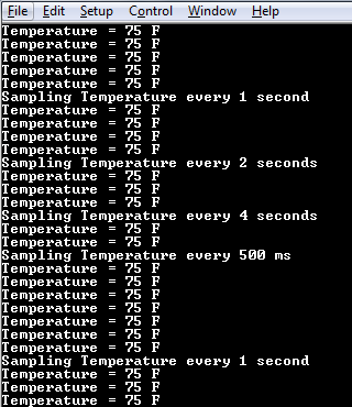
- While the temperature sampling rate changes on every switch SW0 press, notice the LED0 toggling at the same sampling rate.
- Press any character on the terminal
to display the last five values written to the EEPROM. Notice that a red LED (LED1)
will be toggled when a key is pressed in the serial console to read the temperature
values from the secure EEPROM.
- Anytime press SW1 to start running basic functionality shown in Basic Functionality.
Comments
- Dual Developer Application Development Use Case with
TrustZone on SAM L11 Using MPLAB Harmony v3 (DS90003306).Note: Though this technical brief is on SAM L11 MCUs, the TrustZone concepts it describes also applies to PIC32CM MC LS00 MCUs.
- This application demo builds and works
out of box by following the instructions above in "Running the Demo" section. If you need
to enhance/customize this application demo, you need to use the MPLAB Harmony v3 Software
framework. Refer links below to setup and build your applications using MPLAB Harmony.
- How to Setup MPLAB Harmony v3 Software Development Framework (DS90003232)
- How to Build an Application by Adding a New PLIB, Driver, or Middleware to an Existing MPLAB Harmony v3 Project (DS90003253)
- Video - How to Set up the Tools Required to Get Started with MPLAB® Harmony v3 and MCC
- Create a new MPLAB Harmony v3 project using MCC
- Update and Configure an Existing MHC-based MPLAB Harmony v3 Project to MCC-based Project