
1.2.3 Curiosity PIC32MZ EF 2.0 Development Board: Building and Running the UDP Live Update Applications
Downloading and Building the Application
To clone or download this application from Github, go to the main page of this repository and then click Clone button to clone this repo or download as zip file. This content can also be download using content manager by following these instructions.
Path of the application within the repository is apps/udp_live_update/.
To build the application, refer to the following table and open the project using its IDE.
Switcher Application
| Project Name | Description |
|---|---|
| switcher/firmware/pic32mz_ef_curiosity_v2.X | MPLAB X Project for Curiosity PIC32MZ EF 2.0 Development Board |
Live Update Application
| Project Name | Description |
|---|---|
| live_update_app/firmware/pic32mz_ef_curiosity_v2.X | MPLAB X Project for Curiosity PIC32MZ EF 2.0 Development Board |
Setting Up Curiosity PIC32MZ EF 2.0 Development Board
- For programming and UART console, connect a micro USB cable to the USB Debug port J700
- Mount a LAN8740 PHY daughter board on to the Ethernet PHY Module connector
- Establish a connection between Host PC and the device through the RJ45 Ethernet connector on the LAN8740 PHY daughter board using an Ethernet cable
Running the Application
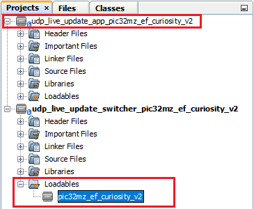
- Open the Switcher application project switcher/firmware/pic32mz_ef_curiosity_v2.X in the IDE.
- Ensure that the
live_update_app/firmware/pic32mz_ef_curiosity_v2.X is added as a
loadable project to Switcher application.
- As the Switcher application does not have any programming capabilities. Adding the live_update_app as loadable allows MPLAB X to create a unified hex file and program both these application in the respective memory location based on the respective linker scripts.
- Open the Terminal application (e.g., Tera Term) on the computer to get Live Update application messages through UART once loaded.
- Configure the serial port settings as follows:
- Baud: 115200
- Data: 8 Bits
- Parity: None
- Stop: 1 Bit
- Flow Control: None
- Build and program the Switcher application using the IDE.
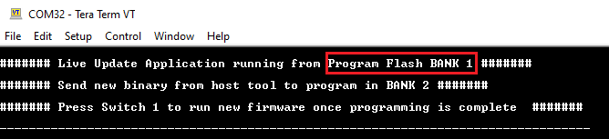
- LED3 should start blinking once
programming is completed and below message has to be displayed on the
console.
- The user can see how the Live Update application was loaded in BANK 1 by IDE and Switcher application jumped BANK 1 to run it
- Configure the Host PC for setting up IP Address to communicate with the
device.
- Go to Control Panel/Network and Internet/Network Connections
- Open Ethernet Properties
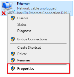
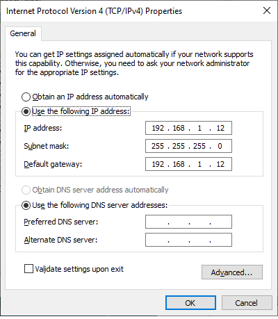
- Double click the Internet Protocol Version 4 (TCP/IPv4)
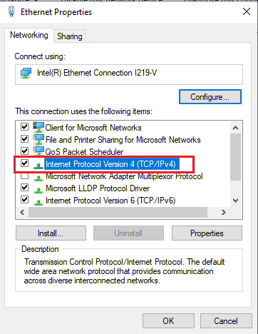
- Configure the IP Address as shown below:
- IP address: 192.168.1.12
- Subnet mask: 255.255.255.0
- Launch the Unified Host application from below path:
- <harmony3_path>/bootloader/tools/UnifiedHost-*/UnifiedHost-*.jar
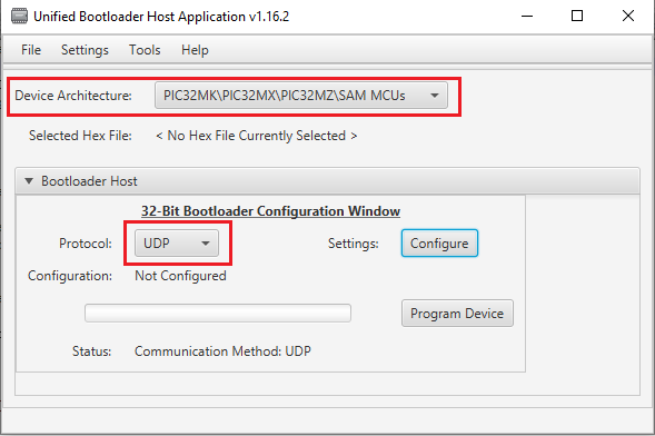
- Configure the Unified host application.
- Select the Device Architecture and Protocol as shown below:
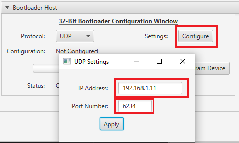
- Click the Configure button to configure UDP Port Number and IP
Address:
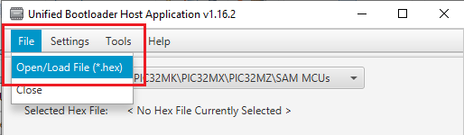
- Load the Live Update
application hex file to be programmed using below option
- <harmony3_path>/bootloader_apps_ethernet/apps/udp_live_update/live_update_app/firmware/pic32mz_ef_curiosity_v2.X/dist/pic32mz_ef_curiosity_v2/production/pic32mz_ef_curiosity_v2.X.production.hex
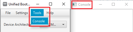
- Open the Console window
of the host application to view application bootloading sequence
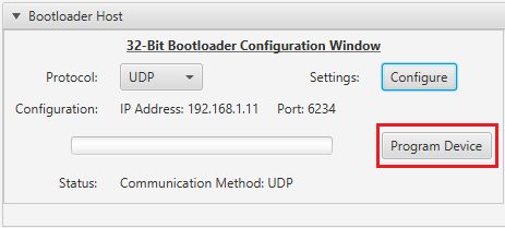
- Select the Device Architecture and Protocol as shown below:
- Click the Program Device
button to program the loaded Live Update application hex file on to the
device.
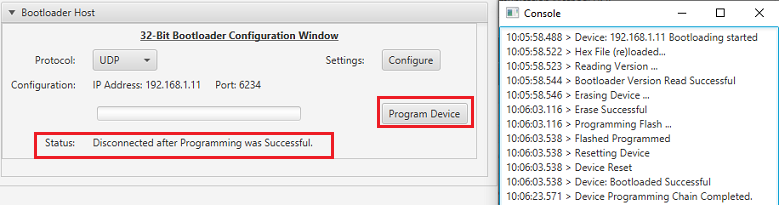
- The user can note that throughout the programming sequence and after programming the LED3 will be blinking as the application task is running along with bootloader task (Live Update Feature)
- Following figure shows output of successfully programming the test
application.
- Ignore the Device Reset Messages from the host tool. The Live Update application ignores the reset command received and waits for a switch press to update serial number and reset.
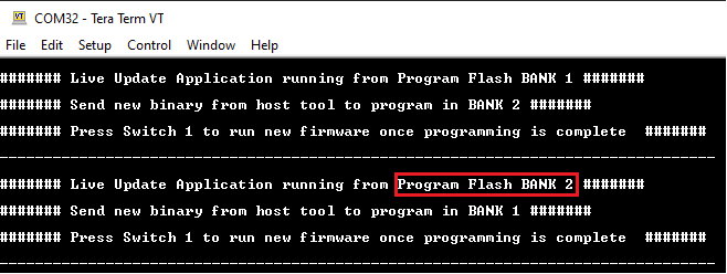
- Press the Switch SW1 to update serial of Inactive Bank and trigger reset. The
user should see below output on success.
- This step shows that the new firmware programmed in BANK 2 is running which is mapped to lower region by switcher at reset
- Repeat Steps 10-12 for further updates and observe the Banks from which application is running at every update.
Configurations to Be Noted
Switcher Application
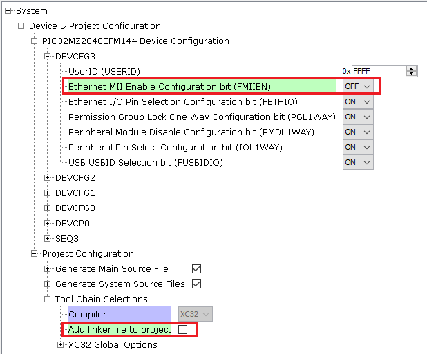
- The UDP Live Update application requires the FMIIEN Device
configuration bit to be set to OFF. This has to be done in Switcher as the
device configuration bits are part of Boot Flash memory and can be only
programmed by Debugger.
- The Device configuration bits of the Live Update application will be discarded
- As custom linker script for
Switcher is being used, the default linker file generation has to be
disabled
Live Update Application
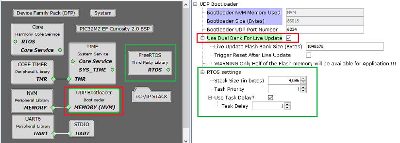
- Enable Live Update option to
configure UDP bootloader in Live Update mode
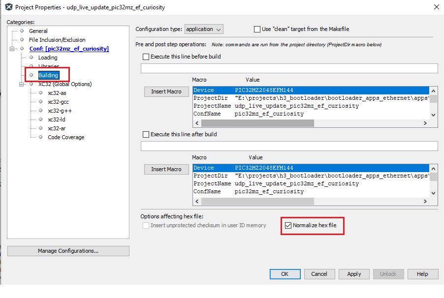
- Normalize hex file:
- Check the Normalize hex file option as shown below, as the Unified
bootloader host application takes hex file as an input. Normalizing
the hex file will ensure the data in the hex file is arranged
sequentially.
- Check the Normalize hex file option as shown below, as the Unified
bootloader host application takes hex file as an input. Normalizing
the hex file will ensure the data in the hex file is arranged
sequentially.