
2.1.1 How the Multi Channel Metrology Driver Library Works
This driver has been designed to be used with PIC32CXMTC devices, which are parts of the PIC32CXMTx device families.
The current version of the multi-channel metrology library is limited to a maximum of two MCP3913/4 devices connected to the MCSPI peripheral. It’s expected to increase that number in future releases.
The Energy Metering AFE collects the data from voltage/current channels and digitizes voltage and current data in any case. This data is processed by the multi-channel metrology library, running on the Core 1 of the PIC32CXMTC part. The multi-channel metrology driver and metering application run on Core 0.
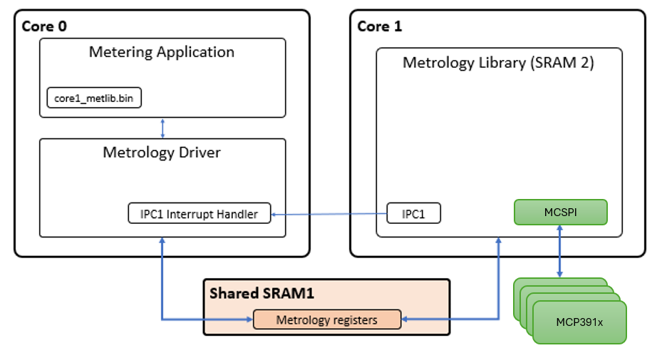
Initialization process
After a power up, the multi-channel metrology driver is responsible of the following points:
- Initialize and configure IPC (Inter-Processor communication) peripheral.
- Initialize the interface with the multi-channel metrology library through shared memory.
- If the reset cause of the main
processor was not a Watchdog reset:
- Control reset lines of the coprocessor (second processor).
- Control clock lines of the coprocessor (second processor).
- Copy the multi-channel metrology library application file to the coprocessor execution memory.
- If the reset cause is Watchdog, no actions are performed with coprocessor, as the system is designed to allow coprocessor continue running if a problem arises only on main processor.
The multi-channel metrology driver provides an assembly file to include the multi-channel metrology library application file into the application of the main processor:
  .section .rodata
  .global met_bin_start
  .global met_bin_end

  .align 8
met_bin_start:
  .incbin "./core1_metlib.bin"
  .align 8
met_bin_end:
A couple of variables are created in order to set the start and end address where the multi-channel metrology library file can be found in the main application.
extern uint8_t met_bin_start;
extern uint8_t met_bin_end;

/* Multi-channel Metrology Driver Initialization Data */
DRV_MCMETROLOGY_INIT drvMCMetrologyInitData = {

    /* MET bin destination address */
    .regBaseAddress = DRV_MCMETROLOGY_REG_BASE_ADDRESS,

    /* MET Binary start address */
    .binStartAddress = (uint32_t)&met_bin_start,

    /* MET Binary end address */
    .binEndAddress = (uint32_t)&met_bin_end,

};
Once the multi-channel metrology library has been located in the main application, the multi-channel metrology driver is in charge of copying its content in the execution memory of the coprocessor.
Once the multi-channel metrology driver has been initialized, it is necessary to call to DRV_MCMETROLOGY_Open() routine which is responsible of enabling IPC peripheral and waiting until multi-channel metrology library application has been started. At this point, metrology control registers are configured and state control data is set to INIT status.
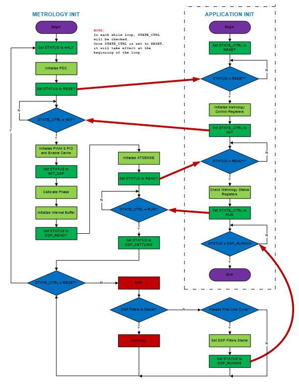
At this point, the application must call the DRV_MCMETROLOGY_GetStatus() routine to wait until the status is equal to DRV_MCMETROLOGY_STATUS_READY. Then the multi-channel metrology driver is ready to be started by the application. For this, the DRV_MCMETROLOGY_Start() routine must be called in order to set the multi-channel metrology library in run mode and receive IPC integration interrupts after each integration period.
Multi-channel metrology library running in the second core is in charge to trigger a new integration period interrupt when the metrology data is ready. This interrupt is handled by the multi-channel metrology driver. After processing the received data, a callback function is used to notify this event to the application.