
2.1.3 Multi-channel Metrology Driver Configurations
Multi-channel Metrology Specific User Configurations
The Multi-channel Metrology Driver library should be configured through MCC. Following is the MCC configuration window for Multi-channel Metrology driver and a brief description.
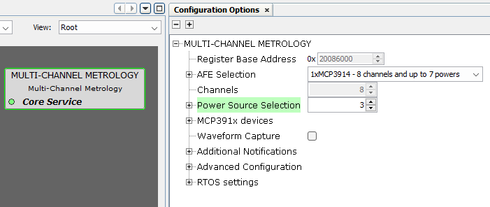
- Register Base Address:
- Specifies the Start Address where the Multi-channel Metrology registers are prefixed.
- AFE Selection:
- Selection of the AFEs
connected to the host MCU. It defines the number of available channels.
Figure 2-5. Multi-channel Metrology AFE Selection 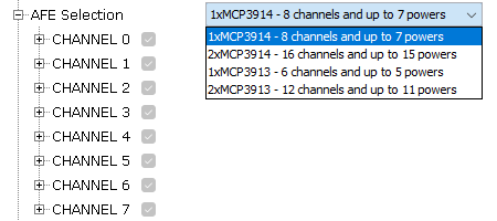
- Selection of the AFEs
connected to the host MCU. It defines the number of available channels.
- Channels:
- Each available channel can be
configured according to the following description:
Figure 2-6. Channel Configuration 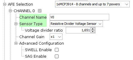
- Channel Name: Description name of the channel. It should be unique.
- Sensor Type: Selects the types of current and voltage sensor used.
Figure 2-7. Sensor Type Selection 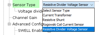
- Current transformer: When this type of sensor is selected, the
channel is considered as a current channel.
Figure 2-8. Current Transformer Current Sensor 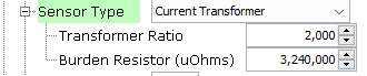
- Resistive Shunt: May only be used with phase-to-neutral voltage
measurement applications. When this type of sensor is selected, the
channel is considered as a current channel.
Figure 2-9. Resistive Shunt Current Sensor 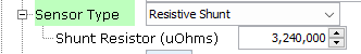
- Rogowski Coil Current Sensor: A digital integrator function is added
to the DSP of all current channels selected as using Rogowski Coils.
When SENSOR_TYPE_CH_x = 2, an additional phase correction is
internally added to each channel with a Rogowski sensor in the
amount of -0.3704º (@ 60 Hz) to correct for a linear phase response
introduced by the digital integrator filter. This is taken into
account during the internal calculation of actual phase-correction
filter coefficients, when a new set of phase calibration settings
are loaded, and must not be added by the user in the
phase-correction entries. When SENSOR_TYPE_CH_x is set to other
values, it takes no effect. When this type of sensor is selected,
the channel is considered as a current channel.
Figure 2-10. Rogowski Coil Current Sensor 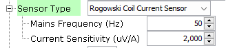
- Resistive Divider Voltage Sensor: Normally, this is the typical
option selected for voltage sensors. When this type of sensor is
selected, the channel is considered as a voltage channel.
Figure 2-11. Resistive Divider Voltage Sensor 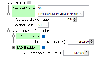
- Current transformer: When this type of sensor is selected, the
channel is considered as a current channel.
- Channel Gain: Programmable Gain Amplifier (G) of the AFE (analog front
end).
Figure 2-12. PGA Gain Selection 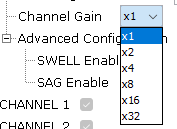
- Advanced configuration:
- SWELL Enable: For
each half cycle of the fundamental period, VxRMS is calculated, per
channel, and compared to the this value to determine if a voltage
swell condition exists. Only valid for voltage channels.
- SWELL Threshold RMS: A SWELL threshold is allowed for each channel and is computed using the native phase voltages before transformation to implied 4WY service. This allows setting different thresholds for non-balanced service types. It must be set in uQ0.32 format.
- SAG Enable: For each
half cycle of the fundamental period, VxRMS is calculated, per
channel, and compared to the this value to determine if a voltage
sag condition exists. Only valid for voltage channels.
- SAG Threshold RMS: A SAG threshold is allowed for each channel and is computed using the native phase voltages, before transformation to implied 4WY service. This allows setting different thresholds for non-balanced service types. It must be set in uQ0.32 format
- SWELL Enable: For
each half cycle of the fundamental period, VxRMS is calculated, per
channel, and compared to the this value to determine if a voltage
swell condition exists. Only valid for voltage channels.
- Each available channel can be
configured according to the following description:
- Power Source Selection: It configures the number of powers computed by the
multi-channel metrology library. A power is defined as a pair of voltage and current
channels, so the maximum number of powers is equal to the maximum number of channels
minus one. The multi-channel metrology library will compute the active and reactive
power associated with each one of the powers enabled.
Figure 2-13. Power Source Configuration 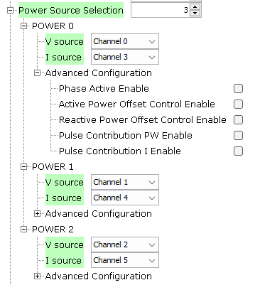
- V Source: Selects the channels with the voltage source of each power.
- I Source: Selects the channels with the current source of each power.
- Advanced Configuration:
Figure 2-14. Power Source Advanced Configuration 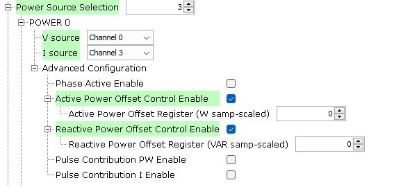
- Phase Active Enable: Not used in this version.
- Active Power Offset Control Enable: It is used to enable per-channel
active power offset added to the 64-bit processing stream.
- Active Power Offset Register: This value indicates the per-power active power offset. The units is [W samp-scaled]. For a fixed voltage, this offset may be computed by applying voltage phase(s), setting zero current(s) and reading the power’s active power accumulator, P_x. Averaging over many readings or a longer integration period may provide a more statistically accurate estimate. It must be set in sQ1.30 format, and its value is subtracted each sample at a 4 kHz rate.
- Reactive Power Offset Control Enable: it is used to enable
per-channel reactive power offset added to the 64-bit processing
stream.
- Reactive Power Offset Register: This value indicates the per-power reactive power offset. The units is [VAR samp-scaled]. For a fixed voltage, this offset may be computed by applying voltage phase(s), setting zero current(s) and reading the power’s reactive power accumulator, Q_x. Averaging over many readings or a longer integration period may provide a more statistically accurate estimate. It must be set in sQ1.30 format, and its value is subtracted each sample at a 4 kHz rate.
- Pulse Contribution PW Enable: Selects the powers used for pulse computation, for all the pulses configured to pulse active or reactive energy. At least one power must be enabled for pulsing to function. This feature may be used to temporarily disable or exclude powers from pulse computation.
- Pulse Contribution I Enable: Selects the currents used for pulse computation, for all the pulses configured to pulse I2. At least one current must be enabled for pulsing to function. This feature may be used to temporarily disable or exclude currents from pulse computation.
- MCP391x devices: Only Dither and boost can be changed in this version.
- Dithering Circuit:
Figure 2-15. MCP391x device Dithering Circuit Configuration 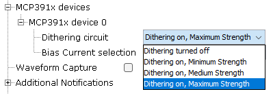
- Bias Current Selection:
Figure 2-16. MCP391x device Bias Current Configuration 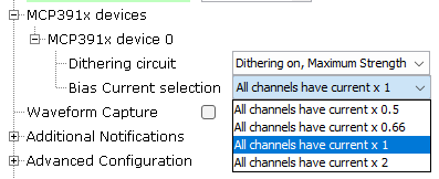
- Dithering Circuit:
- Waveform capture:
Figure 2-17. Waveform Capture Configuration 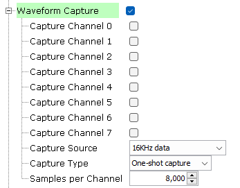
- The waveform capture feature is a powerful tool allowing the Core 0 to access to the metrology samples. The data can be processed by the Demo Meter Application running on Core 0, or can be sent to an external device for being analyzed.
- The waveform capture function
is useful in two main scenarios:
- When the product is being developed it's an excellent engineering tool for analyzing the acquired data. The signals can be inspected in order to obtain additional information about a hypothetical cross-talk, or to assess how some critical sections of the electronic design (power supplies, communications modules, relays, switching devices, ...) could be introducing noise in the metrology channels.
- At the release time, it allows to include new functionality in the final product. Typical examples: waveform monitors, harmonic analysis of the captured data (FFT), and so on.
- Capture channel: Only selected channels are captured.
- Capture Source:
- All captured data is
after Vref compensation has been applied and are scaled values
(normalized by the appropriate K_Ix and K_Vx). In the case of 16 kHz
sampling data, the calibration constants have not been applied.
Possible values are:
- Capture 16 kHz data before DSP filtering.
- Capture 4 kHz FBW data (Full Bandwidth = fundamental + harmonics).
- Capture 4 kHz NBW data (Narrow Bandwidth = fundamental only).
- Capture 8 kHz FBW data (Full Bandwidth = fundamental + harmonics).
- All captured data is
after Vref compensation has been applied and are scaled values
(normalized by the appropriate K_Ix and K_Vx). In the case of 16 kHz
sampling data, the calibration constants have not been applied.
Possible values are:
- Capture Type:
- Capture must be enabled to initiate a capture process. Once enabled, capture occurs based on the requested capture mode. If enabled and a continuous capture mode is selected, capture continues until it is disabled. If enabled and a one-shot capture mode is selected, capture continues until appointed number samples is captured.
- Samples per
Channel:
- Specifies the buffer size used per channel for the capture function in units of 32-bits value.
- Size of the global buffer in bytes where the data set will be stored is obtained as (Num channels) x (Samples per Channel) x 4.
- Additional notifications:
- Additional notifications have different callback functions associated with them. These callback functions are triggered from an interruption context, therefore it is strongly recommended not to put large code inside.
Figure 2-18. Multi-channel Metrology Driver Additional IPC Notifications 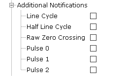
- Line Cycle:
- Enable Line Cycle interrupt.
- This interrupt is generated every full line cycle. It means that the frequency and accumulated energy associated with pulse have been updated. Unlike the RZC_IRQ, the FULL_CYCLE_IRQ uses the 4 kHz narrowband filtered voltage channels and exhibit a deterministic but frequency-dependent phase delay.
- Half Line Cycle:
- Enable Half Line Cycle interrupt.
- This interrupt is generated every half line cycle. It means that swell and sag flags have been updated. Unlike the RZC_IRQ, the HALF_CYCLE_IRQ uses the 4 kHz narrowband filtered voltage channels and exhibit a deterministic but frequency-dependent phase delay.
- Raw Zero Crossing:
- Enable Raw Zero Crossing interrupt.
- This interrupt is generated on zero-crossings using the unfiltered raw 16 kHz data stream of the selected direction and selected voltage channel.
- Pulse 0:
- Enable Pulse 0 interrupt.
- This interrupt is generated immediately after their respective pulse has computationally committed to be generated, but not necessarily occurred, and is not subject to the pulse's PC0_OVERRIDE control bit.
- Pulse 1:
- Enable Pulse 1 interrupt.
- This interrupt is generated immediately after their respective pulse has computationally committed to be generated, but not necessarily occurred, and is not subject to the pulse's PC1_OVERRIDE control bit.
- Pulse 2:
- Enable Pulse 2 interrupt.
- This interrupt is generated immediately after their respective pulse has computationally committed to be generated, but not necessarily occurred, and is not subject to the pulse's PC2_OVERRIDE control bit.
- Advanced Configuration:
Figure 2-19. Multi-channel Metrology Global Configuration 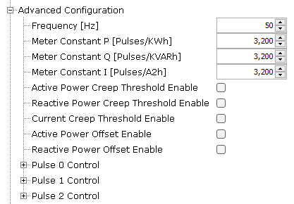
- Frequency: Mains frequency (F). Units: Hz.
- Meter Constant P: Amount of active energy signified by one output pulse. Units: pulses/kWh (active energy).
- Meter Constant Q: Amount of reactive energy signified by one output pulse. Units: pulses/kVARh (reactive energy).
- Meter Constant I: Amount of current signified by one output pulse. Units: pulses/kAmp2-h (amp square).
- Active Power Creep
Threshold Enable:
- Used to
enable/disable metrology creep function of active power pulse
generation and any associated ACC_Tx total energy pulse value
accumulators.
Figure 2-20. Active Power Creep Threshold 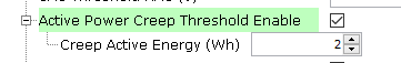
- Creep Active
Energy (Wh):
- Total active energy pulse quantities in any one line cycle interval less than the creep threshold are reset to zero and are not accumulated.
- Is the creep active energy (Watt-hour) in a full cycle (20 ms for 50 Hz, 16.667 ms for 60 Hz).
- Used to
enable/disable metrology creep function of active power pulse
generation and any associated ACC_Tx total energy pulse value
accumulators.
- Reactive Power Creep
Threshold Enable:
- Used to
enable/disable metrology creep function of reactive power pulse
generation and any associated ACC_Tx total energy pulse value
accumulators.
Figure 2-21. Reactive Power Creep Threshold 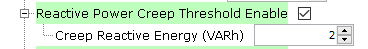
- Creep Reactive
Energy (VARh):
- Total reactive energy pulse quantities in any one line cycle interval less than the creep threshold are reset to zero and are not accumulated.
- Is the creep reactive energy (Var-hour) in a full cycle (20 ms for 50 Hz, 16.667 ms for 60 Hz).
- Used to
enable/disable metrology creep function of reactive power pulse
generation and any associated ACC_Tx total energy pulse value
accumulators.
- Current Creep Threshold
Enable:
- Used to
enable/disable creep function of metrology, both for pulse
generation and any associated ACC_Tx total pulse value accumulators.
Current creep thresholding is used to kill pulse contribution from
any or all phases below the current threshold and affects all
enabled pulsing.
Figure 2-22. Current Creep Threshold 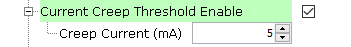
- Creep Current
(mA):
- For each phase in which current is less than this threshold, any contributions to a selected pulse are zeroed out and quantities from that phase make no contribution toward any selected pulse and its associated pulse accumulator.
- Used to
enable/disable creep function of metrology, both for pulse
generation and any associated ACC_Tx total pulse value accumulators.
Current creep thresholding is used to kill pulse contribution from
any or all phases below the current threshold and affects all
enabled pulsing.
- Pulse X Control:
- Three pulses can be
generated at the same time. PULSE0_CTRL is used to control the pulse
output from PD17. PULSE1_CTRL is used to control the pulse output
from PD18. PULSE2_CTRL is used to control the pulse output from
PD19. IPC interrupts are triggered at each pulse: IPC_PULSEx.
Figure 2-23. Multi-channel Metrology Driver Configuration for Pulse X Control 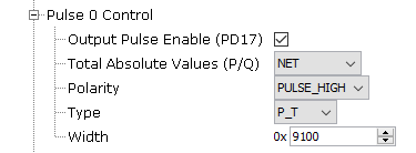
- Output Pulse
Enable:
- Used to enable or disable pulse functionality.
- Total Absolute
Values:
- When creating P and Q accumulator totals of multiple phases, this option allows taking the absolute values of each phase before adding to make the total. This is used to primarily ignore direction of energy delivered/generated, for pulse generation.
- Possible
values are:
- Net: Pulses generated based on (energy delivered – energy generated): Individual sign of each channel’s P and Q is taken into account when creating total P and Q accumulator sums.
- Absolute: Pulses generated based on (energy delivered + energy generated): The absolute value of each phase’s P and Q is used when creating the total P and Q accumulator sums.
- Delivered: Pulses generated based on (delivered only): Only positive values (energy delivered) of each phase’s P and Q are used when creating the total P and Q accumulator sums, with negative values (energy generated) being ignored.
- Generated: Pulses generated based on (generated only): Only negative values (energy generated) of each phase’s P and Q are used when creating the total P and Q accumulator sums, with positive values (energy delivered) being ignored.
- Polarity:
- Pulse Polarity.
- Possible
values are:
- PULSE_LOW: Output pulse is low with width set by K_WIDTH, followed by an inactive level of high.
- PULSE_HIGH: Output pulse is high with width set by K_WIDTH, followed by an inactive level of low.
- Type:
- Possible
values are:
- P_T: Watt-hours, total all phases, fundamental + harmonics.
- P_T_F: Watt-hours, total all phases, fundamental only.
- Q_T: Var-hours, total all phases, fundamental + harmonics.
- Q_T_F: Var-hours, total all phases, fundamental only.
- I_T: Amp-squared-hours, total all phases, fundamental + harmonics.
- I_T_F: Amp-squared-hours, total all phases, fundamental only.
- S_T: VA-hours, total all phases, fundamental + harmonics.
- S_T_F: VA-hours, total all phases, fundamental only.
- S2_T: VA-hours, total all phases, based on sqrt(P2+Q2).
- Possible
values are:
- Width:
- Pulse width.
- The granularity for pulse width is in units of 2.1552 μs.
- Three pulses can be
generated at the same time. PULSE0_CTRL is used to control the pulse
output from PD17. PULSE1_CTRL is used to control the pulse output
from PD18. PULSE2_CTRL is used to control the pulse output from
PD19. IPC interrupts are triggered at each pulse: IPC_PULSEx.
- RTOS Settings
Figure 2-24. Multi-channel Metrology Driver Configuration for RTOS 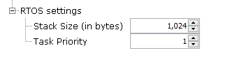
- Stack Size (in
bytes):
- Specifies the number of bytes to be allocated on the stack for the Multi-channel Metrology driver task.
- Task Priority:
- Specifies priority for the Multi-channel Metrology driver task thread. The value can vary based on RTOS used.
- Stack Size (in
bytes):
- NVIC Settings
- IPC1 Interrupt is enabled automatically when using the metrology driver.
- The interrupt priority value
must be set according to the main application. Additional IPC notifications
should be addressed as soon as possible.
Figure 2-25. NVIC Configuration for Multi-channel Metrology Driver 
- Clock Settings
- SRAM1 and IPC1 clocks are
enabled automatically when using the metrology driver.
Figure 2-26. Peripheral Clock Configuration for Multi-channel Metrology Driver 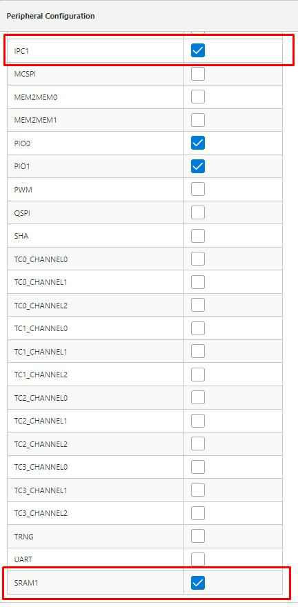
- SRAM1 and IPC1 clocks are
enabled automatically when using the metrology driver.