2.2 Demo Multi-channel Application
Application Description
The Demo Multichannel Application is an example of metering application using the Microchip metrology library with the PIC32CXMTC-DB demonstration kits. The Demo Multichannel application runs in Core 0 of PIC32CXMTC device, while the metrology library is running independently in Core 1.
The Demo Multichannel application software shows how to initialize the Core 1 and the multichannel metrology library, and how to interact with the metrology library using the shared memory area and the IPC interrupts. Additionally, it includes several examples of typical features of a metering application (energy accumulation, storage in non-volatile memory, LCD management, low power modes, …).
Accordingly, the demo multichannel software should be considered as an useful tool to evaluate the features of the multichannel metrology library and to speed up the development of the multichannel application. But it is not intended to be a fully featured and complete implementation of a commercial meter. The meter manufacturer is responsible for the final application development, meeting the required standards, regulatory requirements and features desired for the product The Energy Metering AFE collects the data from current sensors and voltage inputs and digitizes voltage and current data. This data is processed by the Multichannel Metrology library, running on the Core 1 of the PIC32CXMTC microcontroller.
The Demo Multichannel application has been designed in 2 different ways. One of them uses FreeRTOS as real-time operating system and the other one has been designed in baremetal mode to process data and events
- Smart Meter Demonstrator
- Availability of total and per channel measurements: V, I, Wh, VArh, VAh, I2h
- Availability of total fundamental and harmonics, total fundamental only and per channel measurements: V, I, Wh, VArh, VAh, I2h
- Terminal command interface allows user to access the Microchip Metrology Library, configure the system parameters, display measurement results and line voltage status
- Display cumulative energy Wh, momentary energy Wh, power unit, energy flow, energy flow direction and miscellaneous icons
- Meter default configuration, meter configuration saving and loading in non-volatile memory
- Power fail detection and measurements saving and restoring in non-volatile memory
- LCD display management
- Support Rogowski, Current Transformer and Shunt current sensors
- Line voltage monitor per phase: swell, sag, zero-crossing, frequency
- ADC samples data capture
- Total 3 output pulses with pulse source selection
- Metrology application: Handle the multichannel metrology driver and its configuration.
- Energy application: Interact with the metrology application to gather energy consumption. Energy consumption is assigned and grouped into different time zones. This application manages the RTC peripheral.
- Events application: Interact with the metrology application to store the event happening and its occurrence time.
- Console application: Interact with the application using a serial port to send commands to the board and receive data.
- Datalog application: Write/Read data information to/from the external Flash memory.
- Display application: Navigate through the different data shown in the display using the buttons Scroll-down and Scroll-up of the demo boards.
Boards Overview
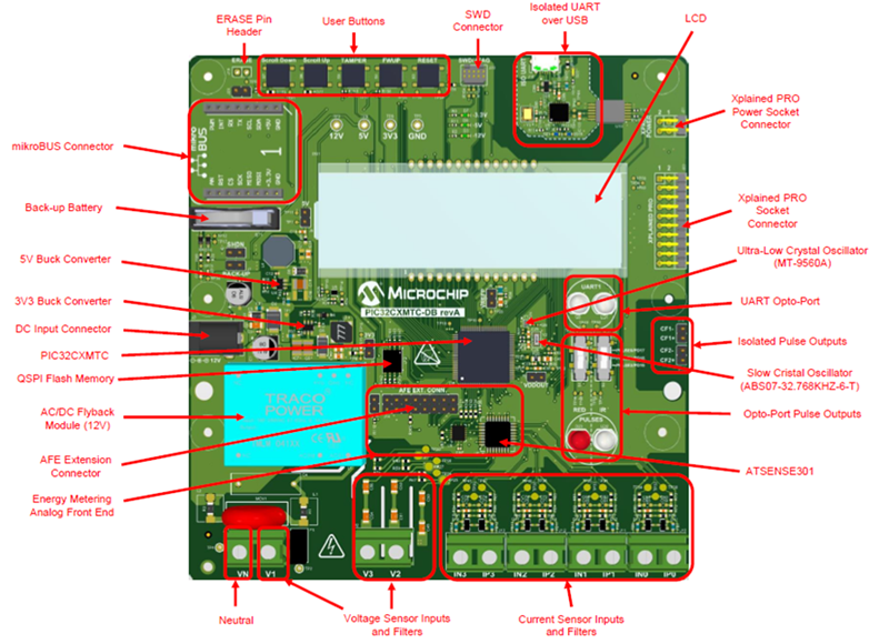
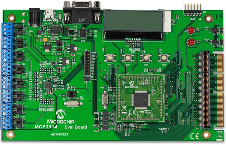
The following pictures show a global overview of the boards. For a detailed description, refer to the “PIC32CXMTC-DB HW User Guide” (DS50003248) and the MCP3914 EVALUATION BOARD.


Unpacking the Kit
To run the multichannel demo, the following addition hardware are required.
- One PIC32CMXMTC-DB board mounted in a protective enclosure.
- One Micro A/B-type USB cable.
- One Arm-JTAG-20-10 adapter.
- One Power Supply adapter (AC/DC) 12 VDC.
- One MCP3914 Evaluation Board (ADM00523)
- One PIC24FJ256GA110 PIM
- One Mini-USB cable
