
1.2.3 Adjust Demo Meter Board for Testing
It is recommended that the PIC32CXMTx-DB boards be customized for the meter rated voltage, current and for the selected sensors.
Voltage Dividers Adjustment
The signal applied to the voltage input connectors of the demo board is reduced by means of resistor voltage dividers. All the evaluation boards use the same divider configuration, so the divider ratio is the same for all the boards and all the phases. The default value is 1651:1, allowing voltage inputs up to 291 Vrms (Vmax). The maximum input voltage supported can be calculated according to the following equation:
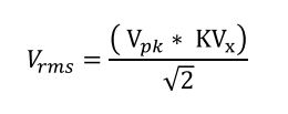
Where:
- Vpk is the peak voltage at the voltage channels metrology inputs of the metering unit. Its typical maximum value is 0.25V.
- KVx is the voltage divider ratio. The default value is 1651.
The metrology voltage divider ratio values are configured into the metrology library by means of the control registers, K_Vx. Refer to the “Microchip PIC32CXMTx Metrology User Guide” (DS50003460), which includes configuration examples. The K_Vx values can be read using the terminal command DCR and written using the command DCW (see Commands for Accessing the Metrology Registers).
Current Network Adjustment
The PIC32CXMTSH-DB board includes two differential current inputs for two phases (A and B), and the PIC32CXMTC-DB board has four differential current inputs for three phases (A, B and C) and neutral current (N).
The hardware of the boards is configured by default to connect Current Transformers, with the same burden resistor value for all the phases (3.24 ohm). It is possible to re-configure the hardware to support other current sensor types, as it is explained in the “PIC32CXMTSH-DB HW User Guide” (DS50003024) and in the “PIC32CXMTC-DB HW User Guide” (DS50003248).
The default CT sensor has a 2000:1 turn ratio. This default configuration allows currents up to 220A (Imax) to be applied. The maximum input current supported can be calculated according to the following equation:
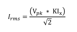
- Kix = (CTratio) / (GPGAx * RBurden). GPGAx is the gain setting of the programmable gain amplifier of the current channels.
- Vpk is the peak voltage at the current channels metrology inputs of the metering unit when GPGAx = 1. Its typical maximum value is 0.5V.
The KIx values are configured into the metrology library by means of the control registers, K_Ix. Refer to the “Microchip PIC32CXMTx Metrology User Guide” (DS50003460), which includes configuration examples for current transformers, Rogowski coils, and shunt resistors. The K_Ix values are entered in the Demo Meter application using the terminal command DCW. The GPGAx values are configured into the metrology library by means of the control registers, ATSENSE ADC Control. If GPGAx values are changed, the systems needs to be reset for the AFE to apply the new values. Refer to the Meter Demo Commands Description and Examples for additional information.
Depending on the maximum current to be applied, the user can adjust the system by changing the current transformer ratio, the burden resistors value or the programmable gain amplifiers. This a highly flexible system allowing different configurations.