
4.1 MCC Generated Code
- Create a new MPLAB X IDE project for PIC18F47Q10.
- Open MCC from the toolbar (for details on how to install the MCC plug-in, see References).
- Go to Project Resources →
System → System Module and do the following configurations:
- Oscillator Select: HFINTOSC
- HF Internal Clock: Select 1_MHz
- Clock Divider: 1
- In the Watchdog Timer Enable field in WWDT tab, ensure ‘WDT Disabled’ is selected
- In the Programming tab, ensure Low-voltage Programming Enable is checked
- Open the Pin Manager → Grid View
window, select UQFN40 in the MCU package field, and make the following pin
configurations:
Figure 4-1. Pin Mapping 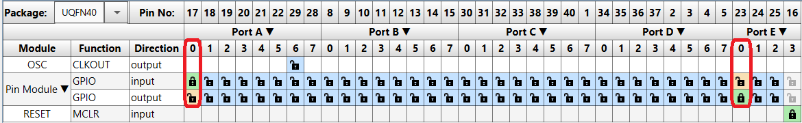
- Go to Project Resources
→ System → Pin Module → Easy Setup and do the following
configurations:
- RA0 Custom Name: RA0
- RA0 WPU: checked
- RA0 IOC: negative
- RE0 Custom Name: LED0
- RE0 Output: checked
- In the Project Resources window, press the Generate button so that the MCC can generate the code capable of configuring the microcontroller as specified.
- In the
main.cfile generated by MCC, add the following code:- Enable the global interrupts
- Add the IOC0 interrupt function
- Set the IOC0 interrupt handler initializer
- Put the device in Sleep
#define DELAY_MS 100

static void IOC0_ISR()
{
    if(IOCAFbits.IOCAF0 == 1)
    {
        ;
    }
}

void main(void)
{
    // Initialize the device
    SYSTEM_Initialize();

    // Enable the Global Interrupts
    INTERRUPT_GlobalInterruptEnable();

    // Disable the Global Interrupts
    //INTERRUPT_GlobalInterruptDisable();

    // Enable the Peripheral Interrupts
    //INTERRUPT_PeripheralInterruptEnable();

    // Disable the Peripheral Interrupts
    //INTERRUPT_PeripheralInterruptDisable();

    IOCAF0_SetInterruptHandler(IOC0_ISR);

    while (1)
    {
        LED0_SetLow();
        __delay_ms(DELAY_MS);
        LED0_SetHigh();

        SLEEP();
    }
}
- Go to Project Resources
→ System → Pin Module → Easy Setup and do the following
configurations:
