
2.1 MCC Generated Code
To generate this project using MPLAB Code Configurator (MCC), follow the next steps:
- Create a new MPLAB X IDE project for PIC18F47Q10.
- Open MCC from the toolbar (for details on how to install the MCC plug-in, see References).
- Go to Project Resources →
System → System Module and do the following configurations:
- Oscillator Select: HFINTOSC
- HF Internal Clock: Select 1_MHz
- Clock Divider: 1
- In the Watchdog Timer Enable field in WWDT tab, ensure ‘WDT Disabled’ is selected
- In the Programming tab, ensure Low-voltage Programming Enable is checked
- Open the Pin Manager → Grid View
window, select UQFN40 in the MCU package field and make the following pin
configurations:
Figure 2-1. Pin Mapping 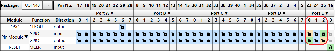
- Go to Project Resources
→ System → Pin Module and do the following configurations:
- RE2 Custom Name: SW0
- RE2 WPU: checked
- RE0 Custom Name: LED0
- RE0 Output: checked
The names used in this examples are ‘LED0’ for the RE0 pin and ‘SW0’ for the RE2 pin.
- In the Project Resources window, press the Generate button so that the MCC can generate the code capable of configuring the microcontroller as specified.
- In the
main.cfile generated by MCC, change or add the following code:while (1) { if(SW0_GetValue()) { LED0_SetHigh(); } else { LED0_SetLow(); } }
- Go to Project Resources
→ System → Pin Module and do the following configurations:
