
1.1.5 SAMA7D65-Curiosity Board: Building and Running the USB Device HID Bootloader With SD/eMMC Media Applications
Downloading and Building the Application
To clone or download this application from Github, go to the main page of this repository and then click Clone button to clone this repo or download as zip file.
Path of the application within the repository is apps/mpu_usb_bootloader/.
To build the application, refer to the following table and open the project using its IDE.
Bootloader Application
| Project Name | Description |
|---|---|
| bootloader_sd_emmc/sama7d65_curiosity.X | MPLABX Project for SAMA7D65-Curiosity Board |
Test Application
| Project Name | Description |
|---|---|
| test_app/sama7d65_curiosity.X | MPLABX Project for SAMA7D65-Curiosity Board |
Setting Up SAMA7D65-Curiosity Board
- Connect the DBGU0 J35 on curiosity board to the computer using a UART-FTDI cable (to enable debug com port)
- Connect the USBA port J3 on the curiosity board to the computer using a Type-C USB cable (to power the board)
- SD Card with FAT32 file system on the Curiosity board
Running the Application
Open the Terminal application (Ex.:Tera Term) on the computer.
Configure the serial port settings as follows:
- Baud: 115200
- Data: 8 Bits
- Parity: None
- Stop: 1 Bit
- Flow Control: None
Open the bootloader project bootloader_sd_emmc/sama7d65_curiosity.X in the IDE.
Build the project to generate the harmony_bootloader.bin binary (Do not program the binary).
Copy the MPU bootstrap loader binary (boot.bin) from <harmony3_path>/bootloader_apps_usb/deps/at91bootstrap_binaries_sama7d65_curiosity/bootloader/sd_card/boot.bin onto the SD Card.
Copy the harmony bootloader binary (harmony_bootloader.bin) from <harmony3_path>/bootloader_apps_usb/apps/mpu_usb_bootloader/usb_device_hid_bootloader/bootloader_sd_emmc/sama7d65_curiosity.X/dist/sama7d65_curiosity/production/harmony_bootloader.bin onto the SD Card.
Insert the SD card into SD BOOT connector J14 on the target board.
Reset or Power cycle the device. Green LED will be turned-on to indicate that harmony bootloader code is running on the target.
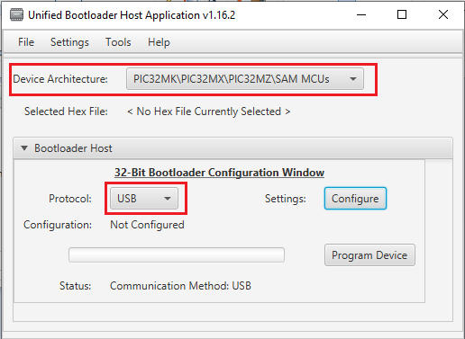
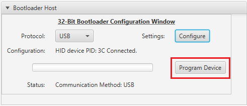
Configure the Unified host application.
Select the Device architecture and Protocol as shown below
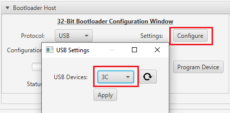
Click the Configure button and select the USB Device as 3C
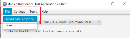
Load the test application hex file to be programmed using below option
- <harmony3_path>/bootloader_apps_usb/apps/mpu_usb_bootloader/test_app/sam_9x75_curiosity.X/dist/sam_9x75_curiosity/production/sam_9x75_curiosity.X.production.hex
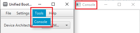
Open the Console window of the host application to view application bootloading sequence
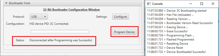
Click the Program Device button to program the loaded test application hex file on to the device.
Following snapshot shows output of successfully programming the test application.
If above step is successful then Green LED should start blinking and the user should see below output on the console.
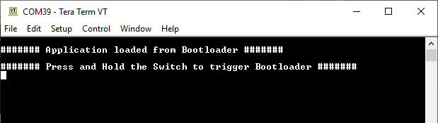
Press and hold the Switch USER and then press Reset button or Power cycle the device to force trigger bootloader at startup.
Repeat Steps 10-12 once.
- This step is to verify whether bootloader is triggered by switch press at reset
Additional Steps (Optional)
To bootload any other application refer to the Application Configurations
Once done repeat the applicable steps mentioned in Running The Application