6.2.4.1 Building and Running the OTA Demo Application
Building the Application
To build this application, open the project file
(
apps\ota_demo\firmware\sam_e54_xpro_rnwf_uart.X/) in MPLAB X
IDE. For more details on opening the project file in MPLAB X IDE, refer to the Opening the
Project file. The following table provides details on the project
file.| Project Name | Description |
|---|---|
sam_e54_xpro_rnwf_uart.X |
|
Running the Application
- Mount the Serial Flash and RNWF02 Add On Board on the mikroBUS Xplained pro extension boards. Connect the RNWF02 connected mikroBUS Xplained pro extension board to the EXTENSION 1 HEADER and Serial Flash connected extension board to EXTENSION 2 HEADER of SAM E54 Xplained Pro evaluation kit as illustrated in the following figure.
-
Figure 6-74. Host companion mode 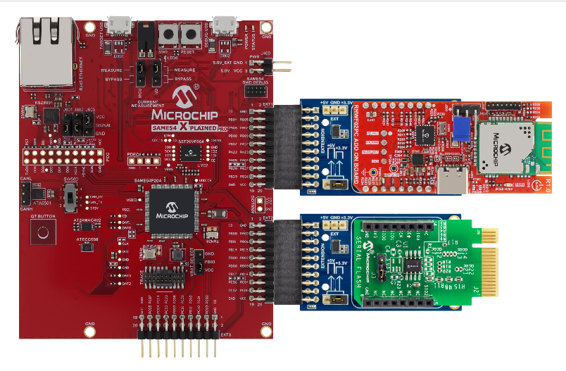
- Connect the debugger USB port on the SAM E54 Xplained Pro evaluation kit to computer using a micro USB cable
- Open the project and launch MCC (Microchip Code Configurator).
- Configure Home-AP credentials
for STA mode, using the Wi-Fi settings configuration. For more details about
the Wi-Fi settings configuration, See Figure 3-64Note: Configure chip-select (CE) for SPI Flash as illustrated in pin settings as shown below
Figure 6-75. SST26_CE 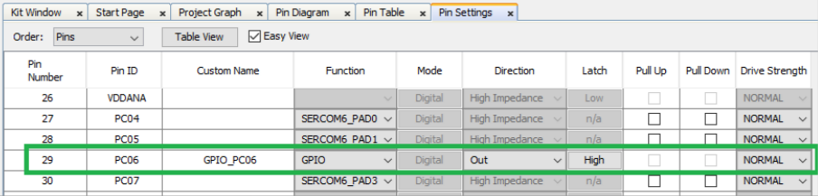
- Generate the code as
illustrated below.
Figure 6-76. Generating the Code 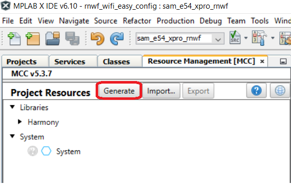
- Build and program the code to
the hardware using MPLAB X IDE
Figure 6-77. Programming the Board 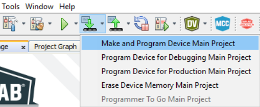
- Open the Terminal application (for example, Tera Term or PuTTY) on the PC
- Connect to the host board
"EDBG Virtual COM Port" and configure the serial settings as follows:
- Baud: 115200
- Data: 8 Bits
- Parity: None
- Stop: 1 Bit
- Flow Control: None
- Press the Reset button on the host board, see Figure .
- The board boots up and
connects to Home-AP, as per the configurations given in step 4. After the
successful Wi-Fi connection the device opens up a TCP tunnel and wait for
the OTA server and firmware image details from the configurator tool.
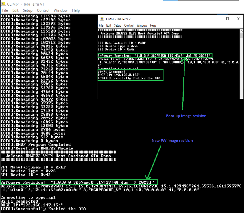
Figure 6-78. Initial Firmware Version, OTA Enable 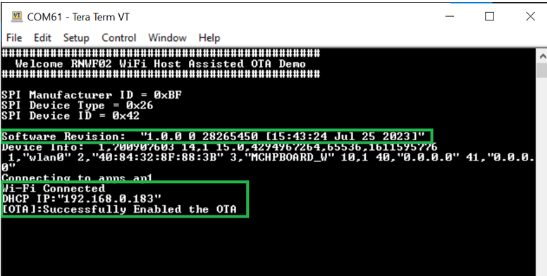
- Two example sample firmware
binaries are available in the
./ota_demo/toolsfolder, start a python HTTP server using the following command.- From File explorer,
navigate to the folder (
./ota_demo/tools)Figure 6-79. Tools Folder 
- In the address bar,
type cmd and hit enter
Figure 6-80. CMD 
- This will open up a
terminal window, located in this folder
Figure 6-81. Terminal Window 
- Start an HTTP server,
enter
python -m http.server. By default it will be listening on port 8000Figure 6-82. python -m http.server 
- From File explorer,
navigate to the folder (
- Run the python OTA
configurator tool from the
./ota_demo/toolsfolder, as illustrated in the following figure- From File explorer,
navigate to the folder (
./ota_demo/tools)Figure 6-83. Tools Folder - In the address bar,
type cmd and hit enter
Figure 6-84. CMD - This will open up a
terminal window, located in this folder
Figure 6-85. Terminal Window - Run the python OTA
configurator by typing
python mchp_configurator.py. Follow the instructions on the terminal, enter http server IP, port and filename image you want the RNWF to download.Note: Hit Enter when requested to enter IP and port and it will default to the computer IP and port 8000Figure 6-86. OTA Configurator 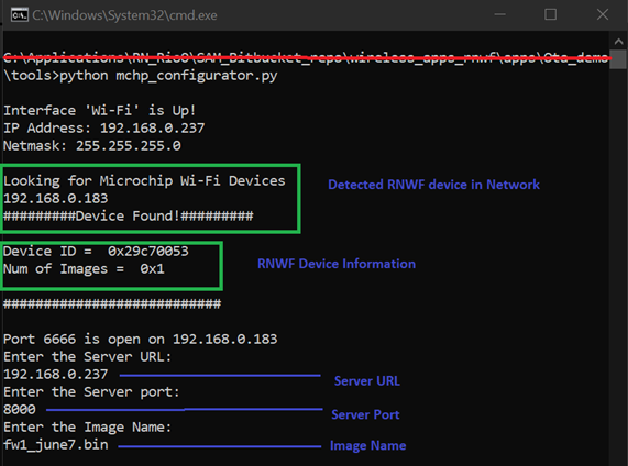
- From File explorer,
navigate to the folder (
- Now the device creates a HTTP
link with the OTA server and starts downloading the image file.
Figure 6-87. Image Download 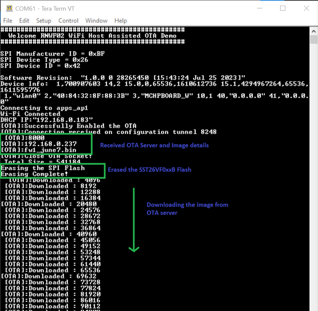
- After successfully
downloading the image, the DFU is triggered and firmware is Flashed into the
RNWF02 module
Figure 6-88. DFU Progress 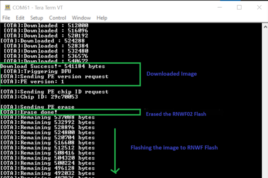
- Upon successful DFU, the host
will Reset and print the RNWF02 module’s new
firmware information
Figure 6-89. Updated Firmware