
4.3 Example 3 : Timer2 Asynchronous Operation
Timer2 can be used in synchronous mode like Timer0 and Timer1. In addition, an asynchronous mode can be used. See the description of the asynchronous clocking in section Clocking by Asynchronous Clock or the data sheet for details.
Example – Timer Output Compare Interrupt
This example shows how to use the timer output compare interrupt of Timer2. The timer will be configured so that the compare match event occurs every second. This feature could be used to implement a RTC. In this example, however, the port pins will be inverted with every compare match event so that PB5 will be blinking with a frequency of 0.5Hz.
Similar to the previous example, PB5 has to be connected to an LED. In addition, a 32.768kHz crystal has to be mounted on the pins TOSC1/PB6 and TOSC2/PB7 of Port B.
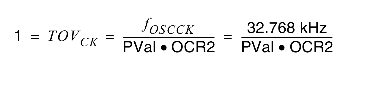
A prescaler value of 1024 is selected plus a corresponding OCR2 value of 32 to get the delay time of one second between two Timer compare match events.
init_Ex3:
	ldi r16, (1<<AS2)
	sts ASSR,r16 ; Enable asynchronous mode
				 ; Clear Timer on compare match. Toggle OC2A on Compare Match
	ldi r16, (1<<COM2A0) | (1<<WGM21)
	sts TCCR2A,r16
				 ; Timer clock = 32768/1024
	ldi r16, (1<<CS22)|(1<<CS21)|(1<<CS20)
	sts TCCR2B,r16
	ldi r16,32
	sts OCR2A,r16 ; Set output compare value to 32
	sbi DDRB, PORTB3 ; Set OC2A pin as output
	lds r16, ASSR ; Refer ATmega328PB datasheet section
				  ;'Asynchronous Operation of Timer/Counter2'
	andi r16, ((1 << OCR2AUB) | (1 << OCR2BUB) | (1 << TCR2AUB) | (1 << TCR2BUB) | (1<< TCN2UB))
	brne PC-0x03
	ldi r16, (1 << TOV2) | (1 << OCF2A) | (1 << OCF2B)
	sts TIFR2,r16 ; Clear pending interrupts
	ldi r16,1<<OCIE2A
	sts TIMSK2,r16 ; Enable timer output compare interrupt
ret void init_Ex3(void)
{
/* Select clock source as crystal on TOSCn pins */
ASSR |= 1 << AS2;
/* Clear Timer on compare match. Toggle OC2A on Compare Match */
TCCR2A = (1<<COM2A0) | (1<<WGM21);
/* Timer Clock = 32768 Hz / 1024 */
TCCR2B = (1<<CS22)|(1<<CS21)|(1<<CS20);
/* Set Output Compare Value to 32. Output pin will toggle every second */
OCR2A = 32;
/* Wait till registers are ready
* Refer ATmega328PB datasheet section
* 'Asynchronous Operation of Timer/Counter2' */
while ((ASSR & ((1 << OCR2AUB) | (1 << OCR2BUB) | (1 << TCR2AUB)
| (1 << TCR2BUB) | (1<< TCN2UB))));
/* Clear pending interrupts */
TIFR2 = (1 << TOV2) | (1 << OCF2A) | (1 << OCF2B);
/* Enable Timer 2 Output Compare Match Interrupt */
TIMSK2 = (1 << OCIE2A);
/* Set OC2A pin as output */
DDRB |= (1 << OC2A_PIN);
}ISR_OCIE2A:
push r16
in r16,SREG
call TOGGLEPIN
out SREG,r16
pop r16
reti
ISR(TIMER2_COMPA_vect)
{
	/* Toggle a pin to indicate compare interrupt */
	PORTB  ^= (1 << USER_LED);
}