
5.2 Hardware Setup
The hardware development boards required for three-phase sequence detection application are connected as shown in Figure 5-2.
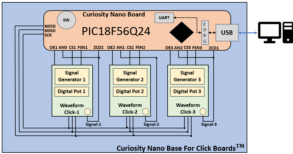
The PIC18F56Q24 Curiosity Nano board is used. It is mounted on a Curiosity Nano Base for Click boards.
The SMA male cable is used to connect the Waveform Clicks’ output to the respective ZCD input and ADCC channel input.
The Data Visualizer tool is used to demonstrate the phase sequence detection application. Graph view of the custom dashboard is used to display the three-phase waveforms generated by the Waveform Clicks to give a visual feedback of the emulated three-phase power supply system. The custom dashboard feature of the Data Visualizer is used to design a dashboard specific for the application. The dashboard shows the fault status. It also allows users to send commands to the emulator to emulate any specific fault condition.
The USB-UART bridge interface on the Curiosity Nano board is used to communicate between the Data Visualizer and the PIC18F56Q24 microcontroller.