7.1 Demo Setup
The following steps explain the procedure for setting up the hardware for the three-phase sequence detection using the PIC18F56Q24 microcontroller.
- Insert the PIC18F56Q24 Curiosity Nano board in the Curiosity Nano slot of Curiosity Nano Base for Click boards. Note: For proper orientation while inserting the Curiosity Nano board, refer to the marking on the Curiosity Nano base board.
- Insert three Waveform Clicks in the three mikroBUS slots (slot 1, slot 2 and slot 3) available on the Curiosity Nano base board.
- Connect the SMA output of the Waveform Clicks to the respective microcontroller I/O pins using SMA connectors, as shown in Table 7-1.
- Connect the Waveform Click outputs to inputs of ADC and ZCD.
- Signal-1 (waveform color - Red) of Waveform Click 1 to the RA0 (ADC AN0 input) and RC2 (ZCD2 input)
- Signal-2 (waveform color - Green) of Waveform Click 2 to the RA1 (ADC AN1 input)
- Signal-3 (waveform color - Blue) of Waveform Click 3 to the RA2 (ADC AN2 input) and RB0 (ZCD1 input)
- Connect the Curiosity Nano board to a host computer (PC) using the type-C USB cable.
- Refer to the Firmware section for firmware and hex file.
- To program application firmware on the microcontroller, refer to the PIC18F56Q24 Curiosity Nano Hardware User Guide.
| mikroBUS™ pin | Microcontroller Pin |
|---|---|
| Waveform Click 1 output signal connector (SMA) | RA0, RC2 |
| Waveform Click 2 output signal connector (SMA) | RA1 |
| Waveform Click 3 output signal connector (SMA) | RA2, RB0 |
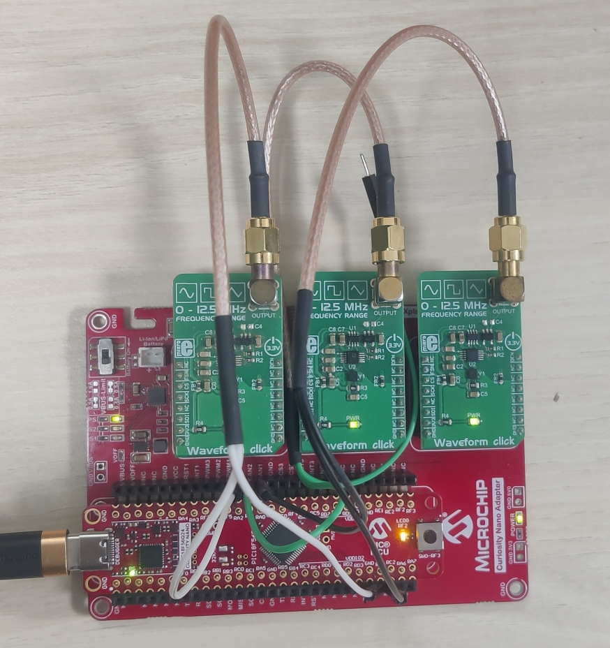
Figure 7-1 shows the hardware setup required for the three-phase sequence detector demonstration.