1.3 Overview – Bipolar Stepper Motor
The motor consists of a rotor, typically a bunch of permanent magnets, and a stator, made of coil pairs wound around a ferromagnetic core. The operation of a bipolar stepper motor is based on the attraction and repulsion between magnetic fields. When applying current to the stator coils, a magnetic field generates and magnetically interacts with the rotor, excreting a force on it.
Idealized and simplified schematic of a stepper motor:
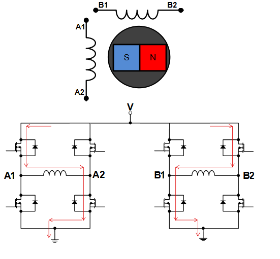
If the stator is being driven by a variable magnetic field, a variable moving magnetic field creates and determines the rotor to follow the varying magnetic field, resulting in mechanical movement. Changing the command angle will reverse the rotation direction.
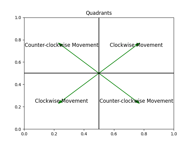
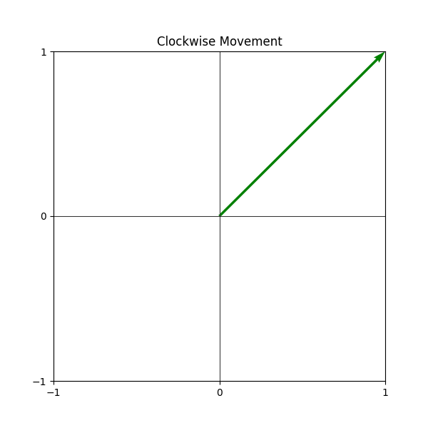
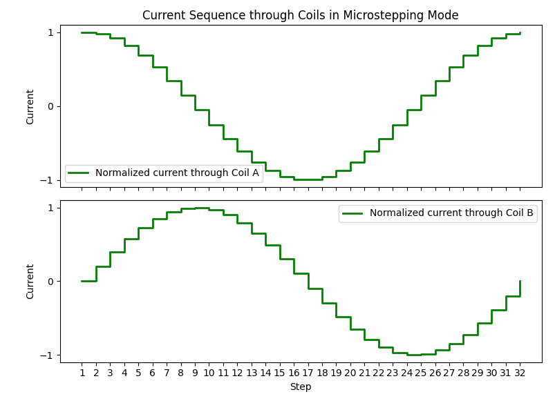
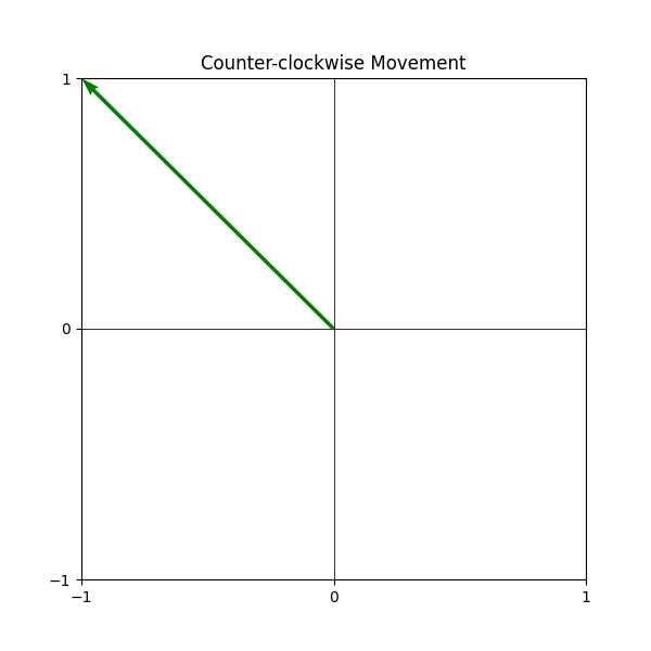
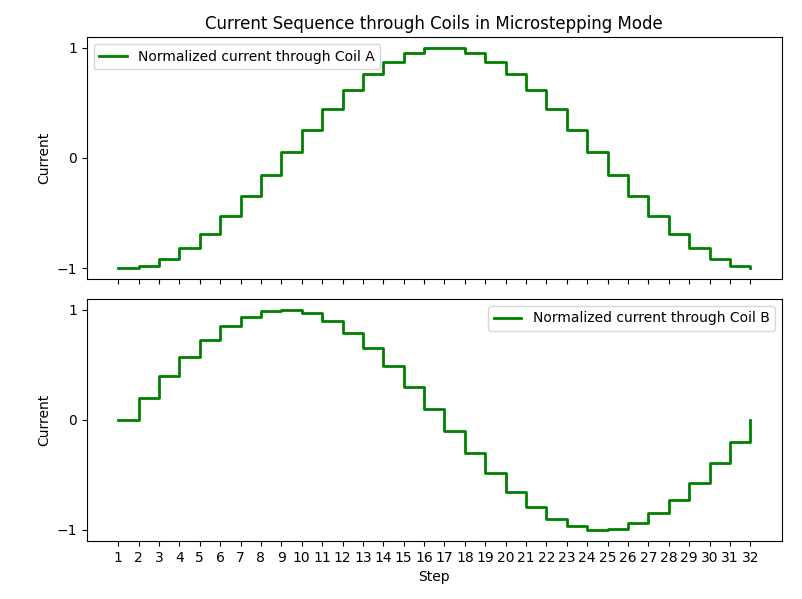
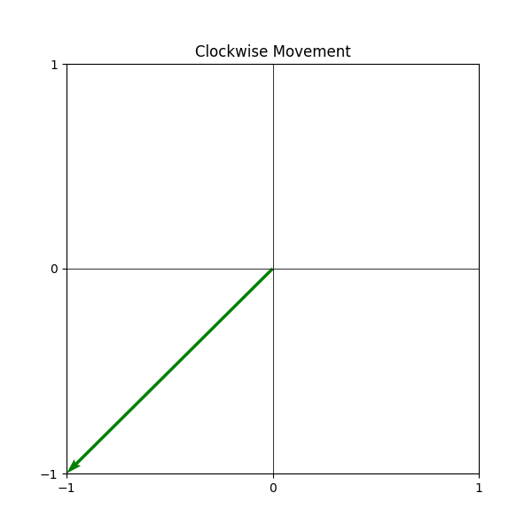
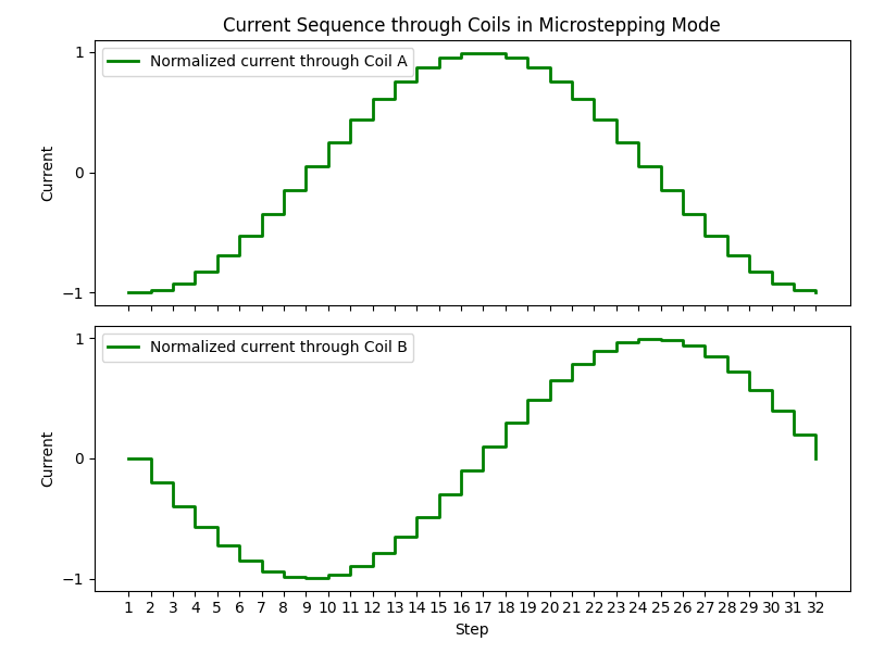
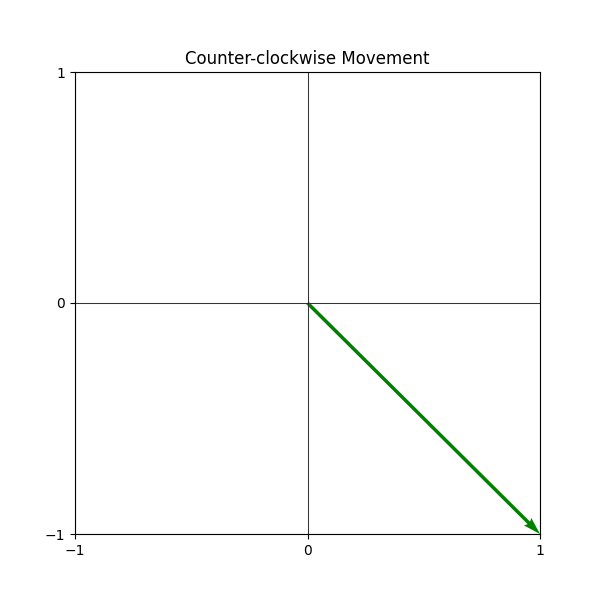
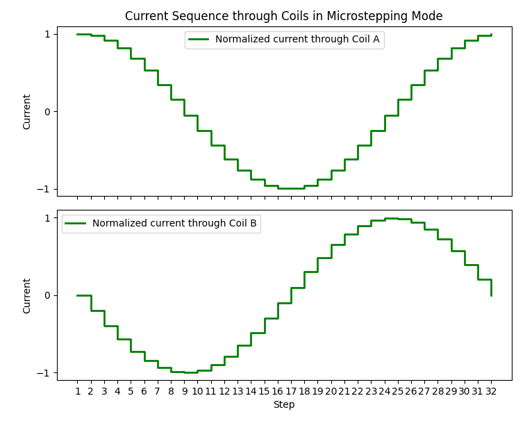
The motor's torque or rotational force is affected by several factors:
- The amount of current supplied to the stator coils directly impacts the strength of the magnetic field and torque
- The number of stator coils also plays a role, with more coils potentially generating a stronger magnetic field and more torque
- The design and material of the rotor can also affect the torque, with a rotor having more poles or made of a material with high magnetic permeability potentially providing more torque
The selected motor for this demo is the 17HS4401 bipolar stepper motor, which has a 1.8º step angle (200 steps/revolution) with 40 Ncm (56 oz-in) holding torque.
The 17HS4401 stepper motor has the following specifications:
• Step Angle: 1.8°
• Holding Torque: 40 Ncm (56 oz-in)
• Rated Current/phase: 1.7A
• Phase Resistance: 1.5Ω ± 10%
• Insulation Resistance: 100 MΩ¸ Min, 500 VDC
• Insulation Strength: 500 VAC for one minute
- I (coil current) = Torque (T) x Kt (torque constant). The torque is directly proportional to the current and the torque constant (Kt).
- Steps per Revolution (SPR) = 360°/Step Angle. This equation calculates the total number of full steps a bipolar stepper motor will take to make one complete 360° rotation. The step angle is the angle turned by the motor for each step. The stepper motor used in the applications has an SPR of 1.8°, giving 200 steps per revolution (360/1.8).
- Speed (RPM) = (Step Frequency x 60)/Steps per Revolution. This equation calculates the speed of the motor in Revolutions per Minute (RPM). The step frequency is the rate at which the control signals change, and steps per revolution is the number of steps the motor takes to complete one full rotation. This equation converts the step frequency into a more commonly used speed metric, RPM.
- Coil Current (I) = Driving Voltage (V)/Coil Resistance (R)
