
1.1.5 I2S Driver Library Help
This section describes the I2S Driver Library.
Introduction
This library provides an interface to manage the I2S Audio Protocol Interface Modes.
Description
The I2S Driver is connected to a hardware module that provides the actual I2S stream, on some MCUs this is a Serial Peripheral Interface (SPI), on others it may be an I2S Controller (I2SC), or Serial Synchronous Controller (SSC).
The I2S hardware peripheral is then interfaced to various devices such as codecs and Bluetooth modules to provide microcontroller-based audio solutions.
Using the Library
This topic describes the basic architecture of the I2S Driver Library and provides information and examples on its use.
Interface Header File: drv_i2s.h
The interface to the I2S Driver Library is defined in the drv_i2s.h header file. Any C language source (.c) file that uses the I2S Driver Library should include drv_i2s.h.
Please refer to the What is MPLAB Harmony? section for how the driver interacts with the framework.
Example Applications:
This library is used by the following applications, among others:
audio/apps/audio_tone
audio/apps/audio_tone_linkeddma
audio/apps/microphone_loopback
Abstraction Model
The I2S Driver provides a high level abstraction of the lower level (SPI/I2SC/SSC) I2S modules with a convenient C language interface. This topic describes how that abstraction is modeled in the software and introduces the I2S Driver Library interface.
Description
Different types of I2S capable PLIBs are available on various Microchip microcontrollers. Some have an internal buffer mechanism and some do not. The buffer depth varies across part families. The I2S Driver Library abstracts out these differences and provides a unified model for audio data transfer across different types of I2S modules.
Both the transmitter and receiver provide a buffer in the driver, which transmits and receives data to/from the hardware. The I2S Driver Library provides a set of interfaces to perform the read and the write. The following diagrams illustrate the abstraction model used by the I2S Driver Library. The I2SC Peripheral is used as an example of an I2S-capable PLIB.
I2S Driver Abstraction Model
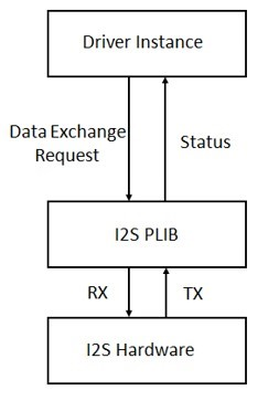
The PLIBs currently provided, such as SSC and I2SC, only support an interrupt/DMA mode of operation. Polled mode of operation is not supported.
Refer to the Driver Library Overwiew section for information on how the driver operates in a system.
The I2S driver library provides an API interface to transfer/receive digital audio data using supported Audio protocols. The library interface routines are divided into various sub-sections, which address one of the blocks or the overall operation of the I2S Driver Library.
| Library Interface Section | Description |
|---|---|
| System Interaction Functions | Provides device initialization and status functions. |
| Client Setup Functions | Provides open and close functions. |
| Data Transfer Functions | Provides data transfer functions. |
| Miscellaneous Functions | Provides driver miscellaneous functions such as get error functions, L/R clock sync, etc. |
| Data Types and Constants | These data types and constants are required while interacting and setting up the I2S Driver Library. |
How the Library Works
The library provides interfaces to support:
System Functionality
Client Functionality

System Access
This section provides information on system access.
System Initialization
The system performs the initialization of the device driver with settings that affect only the instance of the device that is being initialized. During system initialization, each instance of the I2S module would be initialized with the following configuration settings (either passed dynamically at run time using DRV_I2S_INIT or by using Initialization Overrides) that are supported by the specific I2S device hardware:
Device requested power state: one of the System Module Power States. For specific details please refer to Data Types and Constants in the Library Interface section.
The actual peripheral ID enumerated as the PLIB level module ID (e.g., SPI_ID_2)
Defining the respective interrupt sources for TX, RX, DMA TX Channel, DMA RX Channel and Error Interrupt
The DRV_I2S_Initialize API returns an object handle of the type SYS_MODULE_OBJ. The object handle returned by the Initialize interface would be used by the other system interfaces such as DRV_I2S_Deinitialize, DRV_I2S_Status, DRV_I2S_Tasks, and DRV_I2S_TasksError.
1. The system initialization setting only effect the instance of the peripheral that is being initialized.
2. Configuration of the dynamic driver for DMA mode(uses DMA channel for data transfer) or Non DMA mode can be performed by appropriately setting the 'dmaChannelTransmit' and 'dmaChannelReceive' variables of the DRV_I2S_INIT structure. For example the TX will be in DMA mode when 'dmaChannelTransmit' is initialized to a valid supported channel number from the enum DMA_CHANNEL. TX will be in Non DMA mode when 'dmaChannelTransmit' is initialized to 'DMA_CHANNEL_NONE'.
Example:
DRV_I2S_INIT init;

SYS_MODULE_OBJ objectHandle;

_/* I2S Driver Initialization Data */_

DRV_I2S_INIT drvI2S0InitData =

{

.i2sPlib = &drvI2S0PlibAPI,

.interruptI2S = DRV_I2S_INT_SRC_IDX0,

.numClients = DRV_I2S_CLIENTS_NUMBER_IDX0,

.queueSize = DRV_I2S_QUEUE_SIZE_IDX0,

.dmaChannelTransmit = DRV_I2S_XMIT_DMA_CH_IDX0,

.dmaChannelReceive = DRV_I2S_RCV_DMA_CH_IDX0,

.i2sTransmitAddress = (void *)&(SSC_REGS->SSC_THR),

.i2sReceiveAddress = (void *)&(SSC_REGS->SSC_RHR),

.interruptDMA = XDMAC_IRQn,

.dmaDataLength = DRV_I2S_DATA_LENGTH_IDX0,

};

sysObj.drvI2S0 = DRV_I2S_Initialize(DRV_I2S_INDEX_0, (SYS_MODULE_INIT *)&drvI2S0InitData); Task Routine
There is no task routine, since polled mode is not currently supported.
Client Access
This section provides information on general client operation.
General Client Operation
For the application to start using an instance of the module, it must call the DRV_I2S_Open function. This provides the settings required to open the I2S instance for operation.
For the various options available for IO_INTENT, please refer to Data Types and Constants in the Library Interface section.
Example:
DRV_HANDLE handle; handle = DRV_I2S_Open(drvObj->i2sDriverModuleIndex, (DRV_IO_INTENT_WRITE | DRV_IO_INTENT_NONBLOCKING)); if (DRV_HANDLE_INVALID == handle) {

_// Unable to open the driver_ _// May be the driver is not initialized or the initialization_ _// is not complete._

}
Client Operations - Buffered
This section provides information on buffered client operations.
Client buffered operations provide a the typical audio interface. The functions DRV_I2S_BufferAddRead,
DRV_I2S_BufferAddWrite, and DRV_I2S_BufferAddWriteRead are the buffered data operation functions. The buffered functions schedules non-blocking operations. The function adds the request to the hardware instance queues and returns a buffer handle.
The requesting client also registers a callback event with the driver. The driver notifies the client with
DRV_I2S_BUFFER_EVENT_COMPLETE, DRV_I2S_BUFFER_EVENT_ERROR or DRV_I2S_BUFFER_EVENT_ABORT events.
The buffer add requests are processed from the I2S channel ISR in interrupt mode.
The following diagram illustrates the buffered data operations
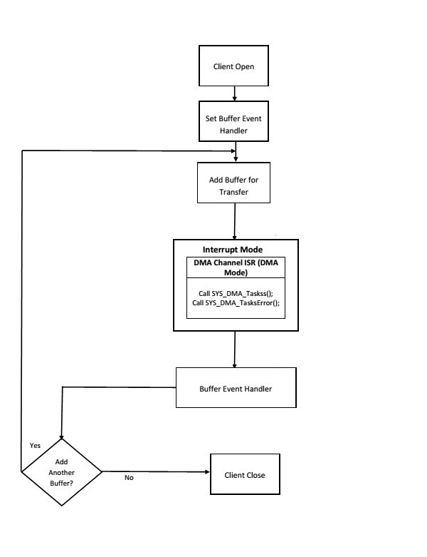
An application using the buffered functionality needs to perform the following steps:
The system should have completed necessary setup and initializations.
If DMA mode is desired, the DMA should be initialized by calling SYS_DMA_Initialize.
The necessary ports setup and remapping must be done for I2S lines: ADCDAT, DACDAT, BCLK, LRCK and MCLK (if required).
The driver object should have been initialized by calling DRV_I2S_Initialize. If DMA mode is desired, related attributes in the init structure must be set.
Open the driver using DRV_I2S_Open with the necessary ioIntent to get a client handle.
The necessary BCLK, LRCK, and MCLK should be set up so as to generate the required media bit rate.
The necessary Baud rate value should be set up by calling DRV_I2S_BaudrateSet.
The Register and event handler for the client handle should be set up by calling DRV_I2S_BufferEventHandlerSet.
Add a buffer to initiate the data transfer by calling DRV_I2S_BufferAddWrite/DRV_I2S_BufferAddRead/DRV_I2S_BufferAddWriteRead.
When the DMA Channel has finished, the callback function registered in step 8 will be called.
Repeat step 9 through step 10 to handle multiple buffer transmission and reception.
When the client is done it can use DRV_I2S_Close to close the client handle.
Example:
_// The following is an example for interrupt mode buffered transmit_

#define SYS_I2S_DRIVER_INDEX DRV_I2S_1 _// I2S Uses SPI Hardware_

#define BUFFER_SIZE 1000 _// I2S initialization structure._

_// This should be populated with necessary settings._

_// attributes dmaChannelTransmit/dmaChannelReceive_

_// and dmaInterruptTransmitSource/dmaInterruptReceiveSource // must be set if DMA mode of operation is desired._

DRV_I2S_INIT i2sInit;

SYS_MODULE_OBJ sysObj; _//I2S module object_ DRV_HANDLE handle; _//Client handle_ uint32_t i2sClock; _//BCLK frequency_ uint32_t baudrate; _//baudrate_

uint16_t myAudioBuffer[BUFFER_SIZE]; _//Audio buffer to be transmitted_ DRV_I2S_BUFFER_HANDLE bufferHandle; APP_DATA_S state; _//Application specific state_ uintptr_t contextHandle; void SYS_Initialize ( void* data ) { _// The system should have completed necessary setup and initializations._

_// Necessary ports setup and remapping must be done for I2S lines ADCDAT,_

_// DACDAT, BCLK, LRCK and MCLK_ sysObj = DRV_I2S_Initialize(SYS_I2S_DRIVER_INDEX, (SYS_MODULE_INIT*)&i2sInit); if (SYS_MODULE_OBJ_INVALID == sysObj) {

_// Handle error_

}

}

void App_Task(void) { switch(state) { case APP_STATE_INIT: {

handle = DRV_I2S_Open(SYS_I2S_DRIVER_INDEX, (DRV_IO_INTENT_WRITE | DRV_IO_INTENT_NONBLOCKING)); if(handle != DRV_HANDLE_INVALID ) { _/* Update the state */_ state = APP_STATE_WAIT_FOR_READY; } } break; case APP_STATE_WAIT_FOR_READY: {

_// Necessary clock settings must be done to generate_

_// required MCLK, BCLK and LRCK_

DRV_I2S_BaudrateSet(handle, i2sClock, baudrate);

_/* Set the Event handler */_ DRV_I2S_BufferEventHandlerSet(handle,App_BufferEventHandler, contextHandle);

_/* Add a buffer to write*/_ DRV_I2S_WriteBufferAdd(handle, myAudioBuffer, BUFFER_SIZE, &bufferHandle);

if(DRV_I2S_BUFFER_HANDLE_INVALID == bufferHandle)

{

_// Error handling here_ } state = APP_STATE_IDLE; } break; case APP_STATE_WAIT_FOR_DONE: state = APP_STATE_DONE; break; case APP_STATE_DONE: {

_// Close done_

DRV_I2S_Close(handle); } break; case APP_STATE_IDLE: _// Do nothing_ break; default: break; }

}

void App_BufferEventHandler(DRV_I2S_BUFFER_EVENT event, DRV_I2S_BUFFER_HANDLE bufferHandle, uintptr_t contextHandle) { uint8_t temp; if(DRV_I2S_BUFFER_EVENT_COMPLETE == event) {

_// Can set state = APP_STATE_WAIT_FOR_DONE;_

_// Take Action as needed_ } else if(DRV_I2S_BUFFER_EVENT_ERROR == event) {

_// Take Action as needed_ } else if(DRV_I2S_BUFFER_EVENT_ABORT == event) { _// Take Action as needed_ } else { _// Do nothing_

}

}

void SYS_Tasks ( void ) {

_/* Call the application's tasks routine */_

APP_Tasks ( );

}
Configuring the Library
The configuration of the I2S Driver Library is based on the file configurations.h.
This header file contains the configuration selection for the I2S Driver Library. Based on the selections made, the I2S Driver Library may support the selected features. These configuration settings will apply to all instances of the I2S Driver Library.
This header can be placed anywhere; however, the path of this header needs to be present in the include search path for a successful build. Refer to the Applications Help section for more details.
System Configuration
Configurations for driver instances, polled/interrupt mode, etc.
Configuring MHC
Provides examples on how to configure the MPLAB Harmony Configurator (MHC) for a specific driver.
Description
When building a new application, start by creating a 32-bit MPLAB Harmony 3 project in MPLAB X IDE by selecting File > New Project. Chose the Configuration name the based on the BSP, and select the appropriate processor (such as ATSAME70Q21B).
In MHC, under Available Components select the appropriate BSP, such as SAM E70 Xplained Ultra. Under Audio_->Templates_, double-click on a codec template such as WM8904. Answer Yes to all questions.
You should end up with a project graph that looks like this, after rearranging the boxes:
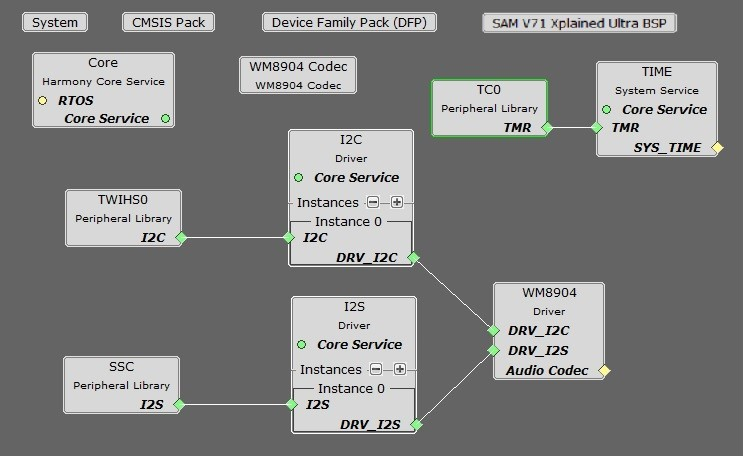
Click on the I2S Driver component, Instance 0, and the following menu will be displayed in the Configurations Options:
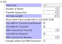
PLIB Used will display the hardware peripheral instance connected to the I2S Driver, such as SPI0, SSC, or I2SC1.
Number of Clients indicates the maximum number of clients that can be connected to the I2S Driver.
Transfer Queue Size indicates number of buffers, of each transfer queue (transmit/receive).
I2S Data Length is the number of bits for one channel of audio (left or right). It must match the size of the PLIB.
Use DMA for Transmit and Receive should always be checked if using DMA, which is currently the only supported mode.
Use DMA for Transmit should be checked if sending data to a codec or Bluetooth module.
DMA Channel for Transmit indicates the DMA channel # assigned (done automatically when you connect the PLIB).
Use DMA for Receive should be checked if receiving data from a codec or Bluetooth module.However if you are only writing to the I2S stream, leaving this checked won't harm anything.
DMA Channel for Receive indicates the DMA channel # assigned (done automatically when you connect the PLIB).
Included Linked List DMA Functions should be checked if using the Linked DMA feature of some MCUs.
You can also bring in the I2S Driver by itself, by double clicking I2S under Harmony_->Drivers_ in the Available Components list. You will then need to add any additional needed components manually and connect them together.
Building the Library
This section lists the files that are available in the I2S Driver Library.
Description
The following three tables list and describe the header (.h) and source (.c) files that implement this library. The parent folder for these files is core/driver/i2s.
Interface File(s)
This table lists and describes the header files that must be included (i.e., using #include) by any code that uses this library.
| Source File Name | Description |
|---|---|
| drv_i2s.h | This file provides the interface definitions of audio/driver/i2s/templates/drv_i2s.h.ftl. (the I2S driver generated via template) |
Required File(s)

This table lists and describes the source and header files that must always be included in the MPLAB X IDE project to build this library.
| Source File Name | Description |
|---|---|
| /src/drv_i2s.c | This file contains the core implementation of the I2S driver with DMA support (generated via template audio/driver/i2s/templates/drv_i2s.c.ftl) |
Optional File(s)
This table lists and describes the source and header files that may optionally be included if required for the desired implementation.
| Source File Name | Description |
|---|---|
| N/A | - |
Module Dependencies
The I2S Driver Library depends on the following modules:
I2S Peripheral Library,
SSC Peripheral Library,
I2SC Peripheral Library
Library Interface
System Interaction Functions
| Name | Description |
|---|---|
| DRV_I2S_Initialize | Initializes the I2S instance for the specified driver index. |
| DRV_I2S_Status | Gets the current status of the I2S driver module. |
Client Setup Functions
| Name | Description |
|---|---|
| DRV_I2S_Open | Opens the specified I2S driver instance and returns a handle to it. |
| DRV_I2S_Close | Closes an opened-instance of the I2S driver. |
Data Transfer Functions
| Name | Description |
|---|---|
| DRV_I2S_ReadBufferAdd | Queues a read operation. |
| DRV_I2S_WriteBufferAdd | Queues a write operation. |
| DRV_I2S_WriteReadBufferAdd | Queues a write/read operation. |
| DRV_I2S_BufferEventHandlerSet | Allows a client to identify a buffer event handling function for the driver to call back when queued buffer transfers have finished. |
| DRV_I2S_ReadQueuePurge | Removes all buffer requests from the read queue. |
| DRV_I2S_WriteQueuePurge | Removes all buffer requests from the write queue. |
| DRV_I2S_BufferStatusGet | Returns the transmit/receive request status. |
| DRV_I2S_BufferCompletedBytesGet | Returns the number of bytes that have been processed for the specified buffer request. |
| Name | Description |
|---|---|
| DRV_I2S_ErrorGet | Gets the I2S hardware errors associated with the client. |
| DRV_I2S_LRCLK_Sync | Synchronize to the start of the I2S LRCLK (left/right clock) signal |
| DRV_I2S_SerialSetup | Sets the I2S serial communication settings dynamically. |
| DRV_I2S_ClockGenerationSet | Set the clock(PLLA and I2SC GCLK clock) generation values |
| DRV_I2S_ProgrammableClockSet | Set the Programmable Clock |
Data Types and Constants
| Name | Description |
|---|---|
| DRV_I2S_BUFFER_EVENT | Identifies the possible events that can result from a buffer add request. |
| DRV_I2S_BUFFER_EVENT_HANDLER | Pointer to a I2S Driver Buffer Event handler function |
| DRV_I2S_BUFFER_HANDLE | Handle identifying a read or write buffer passed to the driver. |
| DRV_I2S_SERIAL_SETUP | Defines the data required to dynamically set the serial settings. |
| DRV_I2S_BUFFER_HANDLE_INVALID | Definition of an invalid buffer handle. |
Description
This section describes the Application Programming Interface (API) functions of the I2S Driver Library.
Refer to each section for a detailed description.