1.3 HID Basic Keyboard Example (hid_basic_keyboard)
This application demonstrates the ability of the MPLAB Harmony USB Host HID Client Driver to
support to enumerate and operate a HID keyboard device.
Description
This application creates a USB Host application that uses the USB Host Layer, HID Client
driver and HID Keyboard Usage driver to enumerate a USB keyboard and understand keyboard
press release events. The keyboard events are displayed using a terminal emulator on a
personal computer.
Downloading and building the
application
To clone or download this application from Github, go to the main page
of this repository and then click Clone button to clone this repository or
download as zip file. This content can also be downloaded using content manager by following
these instructions.
Following table gives the details of project configurations, target device used,
hardware and its IDE. Open the project using the respective IDE and build it.
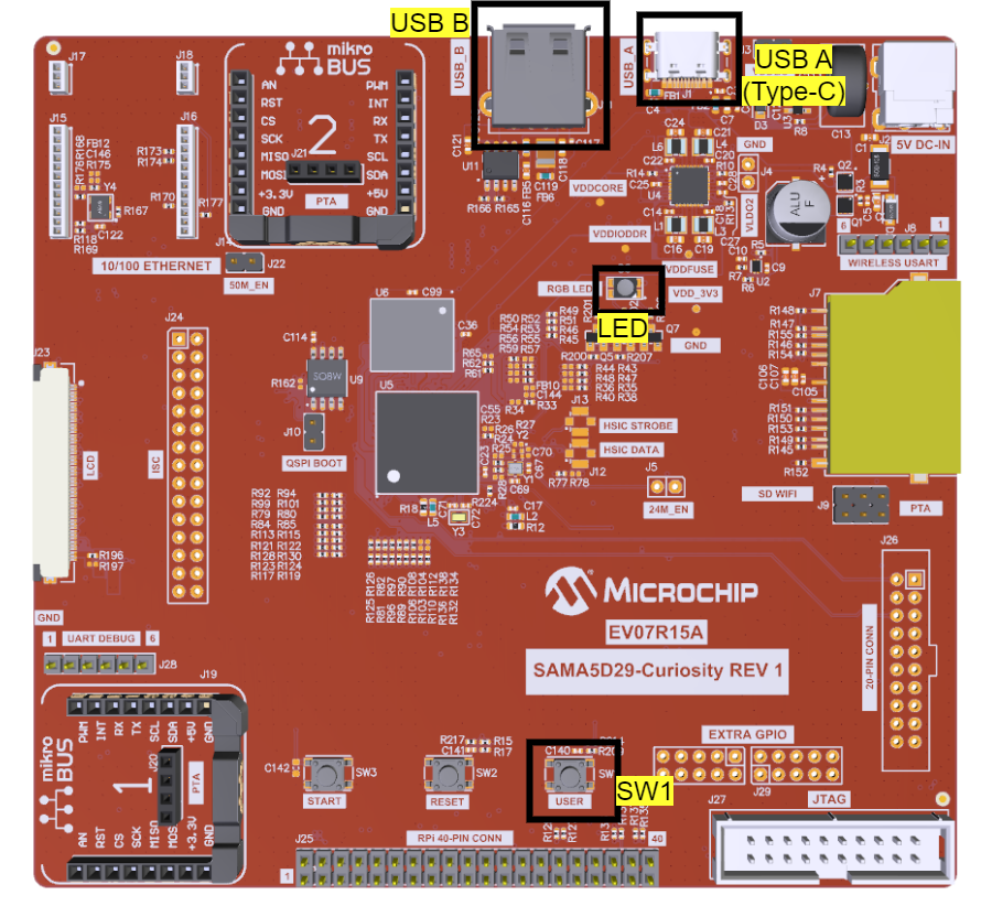
An external power supply (6.5V to 14V)
must be connected through the J200 connector.
A commercially available USB
Keyboard is required to run this demonstration application.
Connect the USB Keyboard to
the USB Type-C connector (J202). A USB Type-C to Type-A Female adapter is required to
connect the USB device to the board (This cable is not included in the kit).
The demonstration uses the
PKOB4 Serial Interface to transfer messages on a PC.
LED1 indicates a Device
Connection. (Attached device has been successfully enumerated and configured).
The LED on the keyboard toggles on
Keyboard "CapsLock" press event.
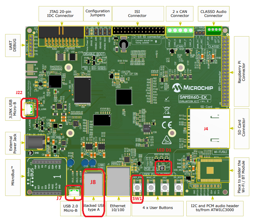
Powered the board with an
external power supply (or use the micro AB connector).
Setup the SD card (Note:
exFAT formatted SD Cards are not supported)
Download harmony MPU
bootstrap loader from this location.
Copy the downloaded boot
loader binary (boot.bin) and generated application binary (harmony.bin) into the SD
card.
Insert the SD card into
the SDMMC connector (SDMMC0) on the board.
Reset the board by
pressing the Push Button RESET, then START.
Connect an USB to serial
cable to DBGU0 (to enable debug com port).
Connect the USB device to the
Type-A connector or to the micro AB with a specific dongle (in these case the need to be
powered by the external power supply).
LED near VDDCORE inscription
on the board is controlled by the attached USB CDC device.SAMD21 Xplained Pro Board
A commercially available
USB Keyboard is required to run this demonstration application.
Jumper titled "PA03
SELECT" must be shorted between PA03 and USB_ID (positions 2 and 3)
Use "TARGET USB"
connector on the board to connect the USB Keyboard to the USB Host. A USB Type-A
Female to micro-B male cable will be needed to connect the device (This cable is not
included in the kit).
The demonstration uses
the EDBG Serial Interface to transfer demonstration application messages on a
PC.
LED0 indicates a Device
Connection. (Attached device has been successfully enumerated and configured).
The LED on the keyboard toggles on
Keyboard "CapsLock" press event.
Note: An unexpected behavior
may be observed if the attached USB device draws an excess amount of current from
the board and the Vdd voltage drops below 2.7 volts. The demo has the wait states
(NVM_CTRLB <RWS[3:0]>) value set to '1'.
A commercially available
USB Keyboard is required to run this demonstration application.
Use "TARGET USB"
connector on the board to connect the USB Keyboard to the USB Host. A USB Type-A
Female to micro-B male cable will be needed to connect the device (This cable is not
included in the kit).
The demonstration uses
the EDBG Serial Interface to transfer demonstration application messages on a
PC.
LED0 indicates a Device
Connection. (Attached device has been successfully enumerated and configured).
The LED on the keyboard toggles on
Keyboard "CapsLock" press event.
A commercially available
USB Keyboard is required to run this demonstration application.
Jumper J203 must be
shorted between PB08 and LED2 (positions 1 and 2).
Use "TARGET USB" J200
connector on the board to connect the USB Keyboard to the USB Host. A USB Type-A
Female to micro-B male cable will be needed to connect the device (This cable is not
included in the kit).
The demonstration uses
the EDBG Serial Interface to transfer demonstration application messages on a
PC.
LED3 indicates a Device
Connection. (Attached device has been successfully enumerated and configured).
The LED on the keyboard toggles on
Keyboard "CapsLock" press event.
An external power supply
(6.5V to 14V) must be connected through the J200 connector.
A commercially available
USB Keyboard is required to run this demonstration application.
Use "TARGET USB" J203
connector on the board to connect the USB Keyboard to the USB Host. A USB Type-A
Female to micro-B male cable will be needed to connect the device (This cable is not
included in the kit).
The demonstration uses
the EDBG Serial Interface to transfer demonstration application messages on a
PC.
LED1 indicates a Device
Connection. (Attached device has been successfully enumerated and configured).
The LED on the keyboard toggles on
Keyboard "CapsLock" press event.
A commercially available
USB Keyboard is required to run this demonstration application.
Chip Erase Jumper must be
open.
Use TARGET USB connector
on the board to connect the USB keyboard to the USB Host. A USB Type-A Female to
micro-B male cable will be needed to connect the device (This cable is not included
in the kit).
The demonstration uses
the EDBG Serial Interface to transfer demonstration application messages on a
PC.
LED0 indicates a Device
Connection. (Attached device has been successfully enumerated and configured).
The LED on the keyboard toggles on
Keyboard "CapsLock" press event.
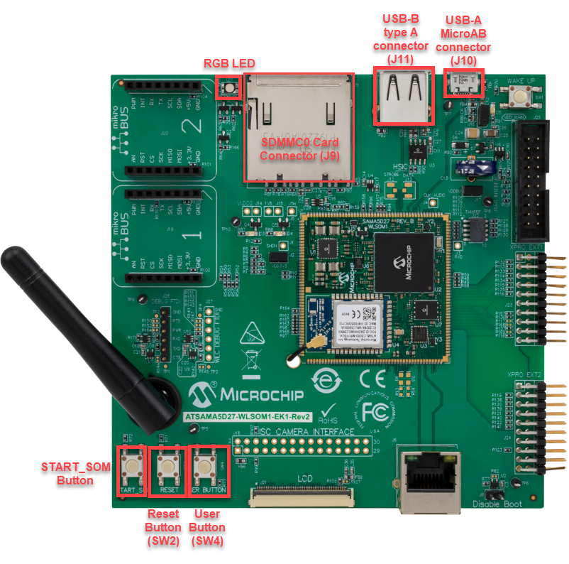
A commercially available USB
Keyboard is required to run this demonstration application.
Setup the SD card (Note: exFAT
formatted SD Cards are not supported)
Download harmony MPU
bootstrap loader from this location.
Copy the downloaded boot
loader binary (boot.bin) and generated application binary (harmony.bin) into the SD
card.
Insert the SD card into the
SDMMC0 Card Connector (J9) on the board.
Reset the board by pressing
the Reset Button (SW2)
Connect the USB-A Micro-AB
connector (J10) on the board to the computer using a micro USB cable.
Press the "START_SOM" button to
activate board start-up.
Connect the USB device to the
USB Type-A connector (J11) on the board.
The demonstration uses the
Debug UART port (J26) to transfer demonstration application messages on a PC. A USB/Serial
converter is required to connect the J26 to a PC (The USB/Serial converter is not included
in the kit).
RGB LED indicates a Device
Connection (Attached device has been successfully enumerated and configured).
The LED on the keyboard toggles
on Keyboard "CapsLock" press event.
A commercially available USB
Keyboard is required to run this demonstration application.
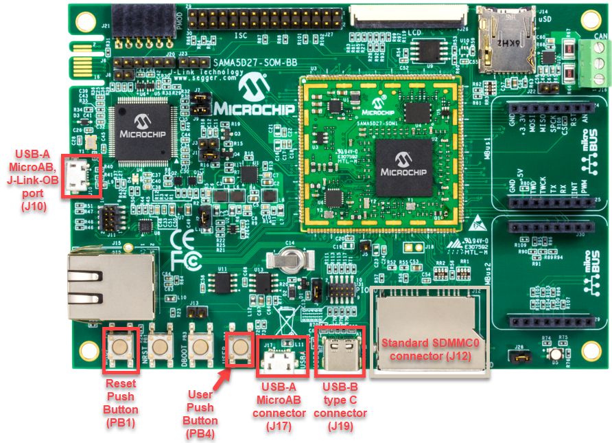
Powered the board with an
external power supply (J1).
Setup the SD card (Note: exFAT
formatted SD Cards are not supported)
Download harmony MPU
bootstrap loader from this location.
Copy the downloaded boot
loader binary (boot.bin) and generated application binary (harmony.bin) into the SD
card.
Insert the SD card into the
SD Card Connector (J4) on the board.
Reset the board by pressing
the Reset Button (nRST)
Press the "nSTART" button to
activate board start-up.
Connect the USB device to the
USB Host Type-A connector (J9) on the board. Alternatively, the USB Device could be
connected to the Type-C connector (J8) or micro A/B connector (J7).
The demonstration uses the
Debug UART port (J24) to transfer demonstration application messages on a PC.
RGB LED indicates a Device
Connection (Attached device has been successfully enumerated and configured).
The LED on the keyboard toggles on
Keyboard "CapsLock" press event.
Setup the SD card (Note: exFAT
formatted SD Cards are not supported)
Download harmony MPU
bootstrap loader from this location.
Copy the downloaded boot
loader binary (boot.bin) and generated application binary (harmony.bin) into the SD
card.
Insert the SD card into the
μSD-CARD connector J6 on the board.(This connector is present on the bottom face of
the board)
Reset the board by pressing
the Push Button RESET.
Press the "START" button to
activate board start-up.
Connect the USB device to the
USB_B Type-A connector (J11) on the board.
RGB LED (D5) on the board indicates a
Device Connection (Attached device has been successfully enumerated and configured).
The LED on the keyboard toggles on
Keyboard "CapsLock" press event.
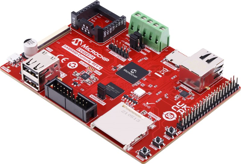
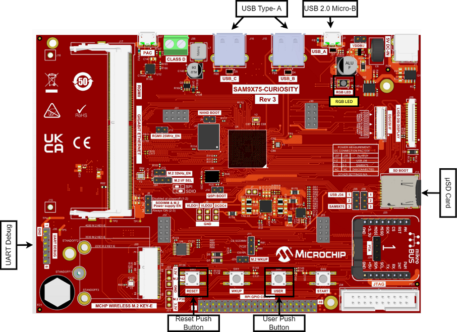
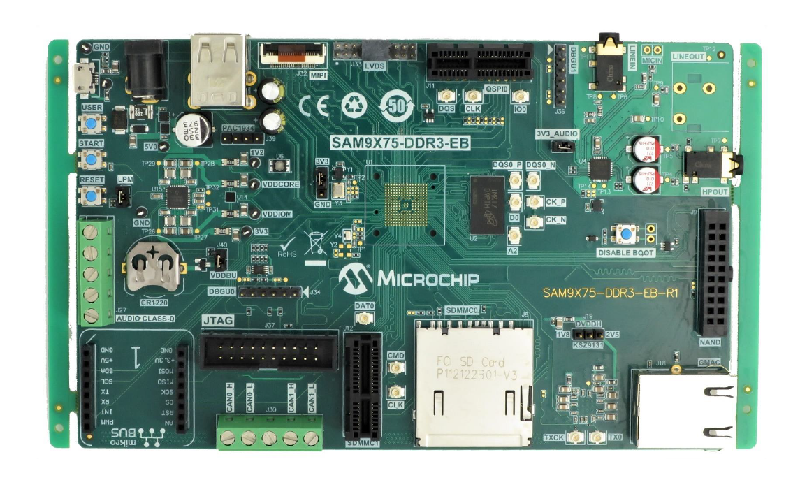
SAM9X75-Curiosity Development Board
Setup the SD card (Note: exFAT
formatted SD Cards are not supported)
Download harmony MPU
bootstrap loader from this location.
Copy the downloaded boot
loader binary (boot.bin) and generated application binary (harmony.bin) into the SD
card.
Insert the SD card into the
μSD-CARD connector (J14) on the board.(This connector is present on the bottom face of
the board)
Reset the board by pressing
the Push Button RESET.
Press the "START" button to
activate board start-up.
Connect the USB device to the
USB_B Type-A connector (J15) or USB_C Type-A connector (J16) on the board.
RGB LED (LD1) on the board
indicates a Device Connection (Attached device has been successfully enumerated and
configured).
The LED on the keyboard toggles on
Keyboard "CapsLock" press event.
The demonstration uses the UART DEBUG
port (J35) to transfer demonstration application messages on a PC. A USB/Serial converter
is required to connect the J35 to a PC (The USB/Serial converter is not included in the
kit).
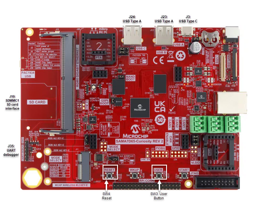
Setup the SD card (Note: exFAT
formatted SD Cards are not supported)
Download harmony MPU
bootstrap loader from this location.
Copy the downloaded boot
loader binary (boot.bin) and generated application binary (harmony.bin) into the SD
card.
Insert the SD card into the
SD-CARD connector (J10) on the board.
Reset the board by pressing
the Push Button RESET.
Press the "START" button to
activate board start-up.
Connect the USB device to the
USB_B Type-A connector (J23) or USB_C Type-A connector (J24) on the board.
RGB LED on the board indicates
a Device Connection (Attached device has been successfully enumerated and configured).
The LED on the keyboard toggles on
Keyboard "CapsLock" press event.
The demonstration uses the UART DEBUG
port (J35) to transfer demonstration application messages on a PC. A USB/Serial converter
is required to connect the J35 to a PC (The USB/Serial converter is not included in the
kit).
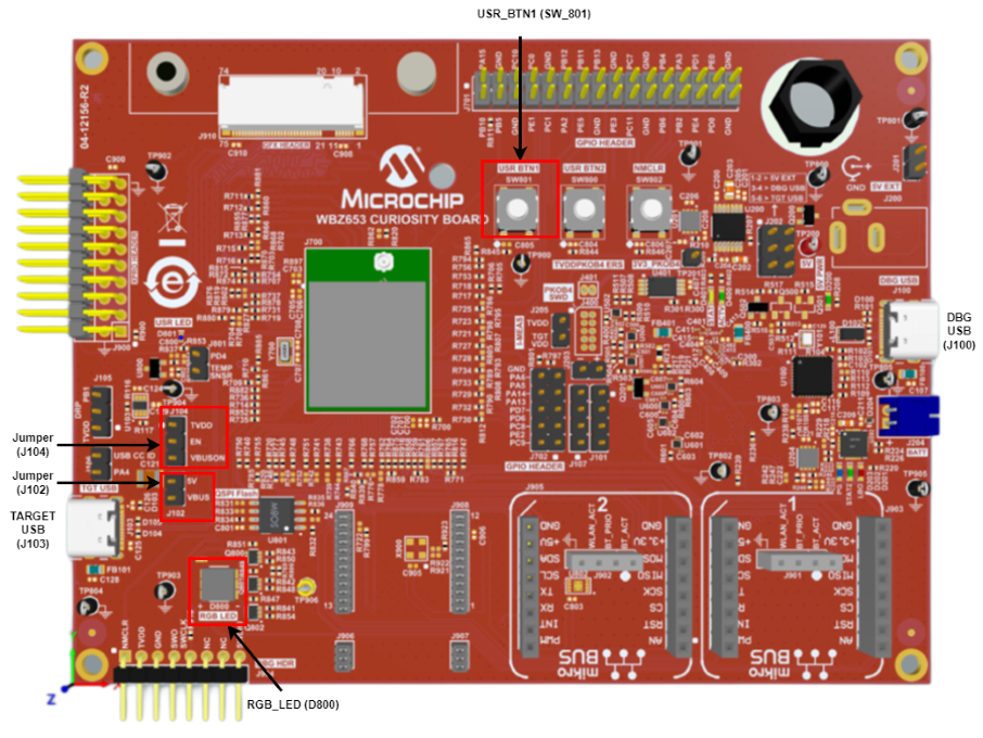
PIC32WM BZ6 Curiosity Board
Connect a Type-C cable between the DBG
USB (J100) port on the board and the PC to power up the board.
The Jumper J102 must be shorted between
5V and VBUS.
The Jumper J104 must be connected between
VBUSON and EN (Positions 2 and 3).
A commercially available USB
Keyboard is required to run this demonstration application.
Connect the USB Keyboard to the
USB Type-C connector TARGET USB (J103). A USB Type-C to Type-A Female adapter is required
to connect the USB device to the board (This cable is not included in the kit).
The demonstration uses the PKOB4 (DBG USB
J100) Serial Interface to transfer messages on a PC.
The RGB_LED (D800) turning
Green indicates a Device Connection. (Attached device has been successfully enumerated and
configured).
The LED on the keyboard toggles on
Keyboard "CapsLock" press event.
A commercially available USB
Keyboard is required to run this demonstration application.
Connect the USB Keyboard to the
connector (J200) using a USB Type-A Female to micro-B male cable (This cable is not
included in the kit).
The demonstration uses the
PKOB4 Serial Interface to transfer messages on a PC.
LED1 indicates a Device
Connection. (Attached device has been successfully enumerated and configured).
The LED on the keyboard toggles
on Keyboard "CapsLock" press event.
Running the Application
Open the project with
appropriate IDE. Compile the project and program the target device.
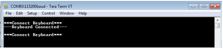
Connect the serial interface
on the board to a PC. On the PC, launch a terminal emulator, such as Tera Term, and
select the appropriate COM port and set the serial port settings to 115200-N-1.
If a USB keyboard is not
connected to the Embedded USB Host, the terminal emulator window will show the Connect
Keyboard prompt.
Attach a USB keyboard to the
Host connector of the target hardware. The message, Keyboard Connected, will appear in
the terminal emulator window. Refer to the Configuring the Hardware section for any
converter requirements.
Begin typing on the keyboard
and the appropriate keys should be displayed on the serial terminal. Subsequent press
and release of modifier keys (i.e., CAPS LOCK, NUM LOCK, etc.) will result in the
appropriate keyboard LEDs to turning ON and OFF.
Disconnecting the keyboard
will result in the message, Connect Keyboard.

 Note: Reset push button on SAM9X60 EK is labeled as SW3.