
4 Creating the LED Blink Application
Now that the project and peripheral setup foundation is complete, this section will show how to configure the hardware (GPIO output) and writing the minimal application logic to blink an LED.
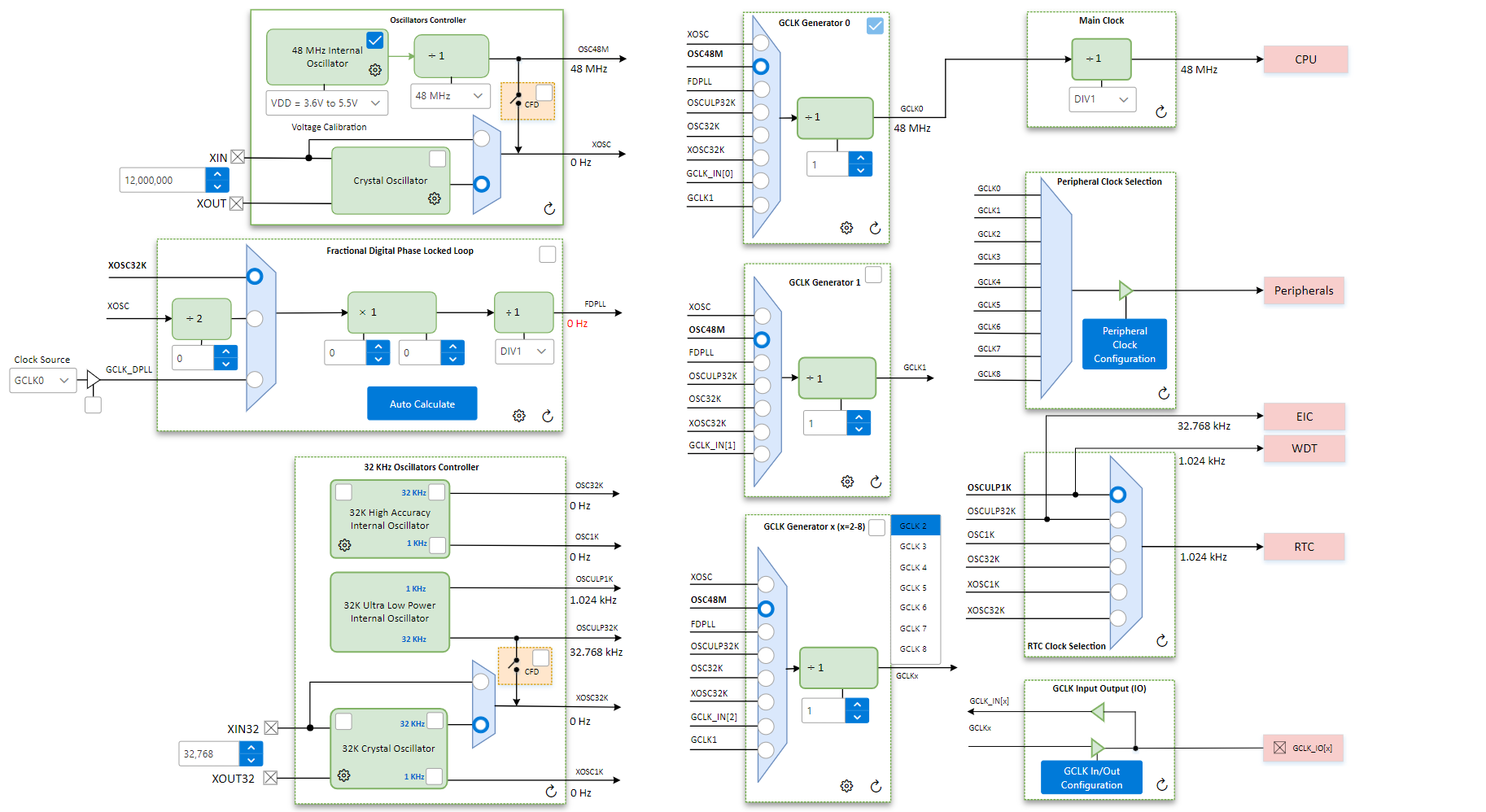
4.1 Step 1. Confirm Clock Settings
Open the Clock Configuration tool from the Plugins section in the Project Graph to verify that the system clock is set to 48 MHz.

The visual interface shows clock sources and dividers, making it easy to check or adjust settings.
4.2 Step 2. Configure the System Timer (SysTick)
SysTick is a built-in timer that allows the application to track time and create precise delays which can be used for blinking an LED. It operates entirely in hardware, so no manual software loops are needed.
To enable SysTick:
- In the Project Graph, select the
System module.

- In the Configuration Options panel, expand Cortex M0+ Configuration.
- Enable the SysTick option.

4.3 Step 3. Configure the Onboard LED
Before configuring the LED in software, we need to identify which pin it is connected to on the Curiosity Nano. According to the Curiosity Nano User Guide, which can be found in the Kit Window of MPLAB X IDE or on the Curiosity Nano landing page, the onboard LED is connected to pin PB17. This is the pin we will configure as a digital output.

- In the Project Graph, go to
Plugins and launch Pin Configuration.

- This opens three configurations tabs for
the pins:
- Pin Settings: Used to
configure pin functionality and properties

- Pin Table: Displays peripheral
functions and their compatible pins

- Pin Diagram: A visual layout showing pin assignments and their availability

- Pin Settings: Used to
configure pin functionality and properties
- In the Pin Settings tab:
- Locate PB17 (Pin #40) in the Pin Table
- Under the Function column, select
GPIO
- This assigns PB17 as a general-purpose I/O, which is necessary for toggling the LED manually in firmware. Without setting it as GPIO, the pin won’t behave as a standard digital output.
- Set the Direction to Out
- Since the LED is an output device, the microcontroller must drive this pin to control it
- Rename the pin to LED using the
Custom Name column
- This allows MCC to generate a named macro or API that makes it easier to reference in the code

4.4 Step 4. Generate the MCC Code
After you finish configuring your project, MCC takes care of generating all the code you need to get started. This includes:
- Configuration bits
- Peripheral setup code
- Easy-to-use functions (called APIs) for things like toggling LEDs or adding delays
To generate code in MCC, click the Generate button in the Project Resources tab in MCC.

You can find these files in the Projects tab, under your project’s Header Files and Source Files folders.

plib_port.h: This header file includes functions MCC created for the LED pin we configured earlier. Since we named the pin LED, you’ll see functions like LED_Toggle() and LED_Set() already available for use in your code.
plib_systick.h: This file includes ready-made functions for using the SysTick timer, like SysTick_DelayMs() to add delays in your program.
If you Ctrl+Click on any of these function names, you’ll jump straight to the actual code
that MCC generated (found in the matching source file, like
plib_systick.c). This is helpful if you want to see how a function
works or what it does behind the scenes.

This is one of the main benefits of using MCC: It gives you a working starting point without having to write all the setup code yourself.
4.5 Step 5. Write the Application Code
Now that configuration is complete, it’s time to write the application logic in
main.c to toggle the onboard LED with a fixed delay. We’ll use functions
that MCC automatically generated based on our earlier setup, no manual register-level coding
needed.
MCC Generated APIs Used:
- SYSTICK_TimerStart()
- Declared in:
plib_systick.h - Defined in:
plib_systick.c - Purpose: Starts the SysTick timer so that delay functions can work
- Declared in:
- LED_Toggle()
- Declared in:
plib_port.h - Defined in:
plib_port.c - Purpose: Toggles the pin we labeled LED in the Pin Manager (PB17). MCC generated this function based on that custom name.
- Declared in:
- SYSTICK_DelayMs(x)
- Declared in:
plib_systick.h - Defined in:
plib_systick.c - Purpose: Delays code execution for a specified number of milliseconds
- Declared in:

main.c)int main(void) { /* Initialize all modules */ SYS_Initialize(NULL); SYSTICK_TimerStart(); while (true) { /* Maintain state machines of all polled MPLAB Harmony modules. */ SYS_Tasks(); LED_Toggle(); SYSTICK_DelayMs(500); } /* Execution should not come here during normal operation */ return ( EXIT_FAILURE); }
4.6 Step 5. Build and Program the Project
Now that your application code is written and MCC has generated all the supporting files, it's time to compile and load the project onto the Curiosity Nano.
Build the Project: Click the Clean and Build icon  on the MPLAB X IDE toolbar. This
compiles the code and confirms everything is configured correctly.
on the MPLAB X IDE toolbar. This
compiles the code and confirms everything is configured correctly.
Check the Output window to ensure the build is completed successfully.

Program the Device: Make sure the Curiosity Nano is connected via USB. Click the Make and
Program Device icon  on the
MPLAB X IDE toolbar to flash the firmware onto the board.
on the
MPLAB X IDE toolbar to flash the firmware onto the board.
Check the Output window to ensure Programming was completed successfully.

Once successful, the onboard LED will begin blinking with a 500 ms delay.


4.7 Step 7. Wrap Up
Now that your LED is blinking, you’ve successfully created a simple embedded application using MPLAB Harmony v3 and the PIC32CM JH/GV Curiosity Nano. Along the way, you:
- Explored the Harmony v3 MCC interface
- Used graphical tools to configure peripherals like SysTick and GPIO
- Leveraged MCC’s auto-generated APIs to write application code without touching a single register
- Built and programmed the project in just a few clicks
This is just the beginning — the same approach can be used to configure UART, I2C, Timers and more. Harmony v3 makes it easy to scale your application as it grows in complexity.