5.2 Multiprotocol Application Demo: Zigbee Light
and Zigbee Commissioning through BLE
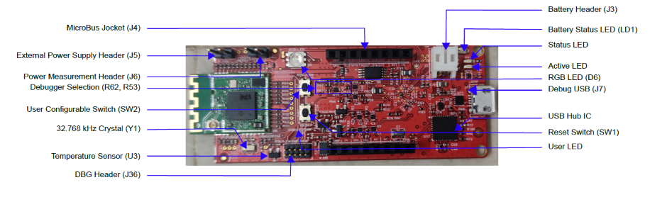
WBZ451 Curiosity
Board
Device: PIC32CX1012BZ25048 (MCU) on WBZ451 Module
On-Board: Analog Temperature
Sensor, RGB LED, User Button, User LED and UART-USB Converter
Figure 5-30. WBZ451 Curiosity Board
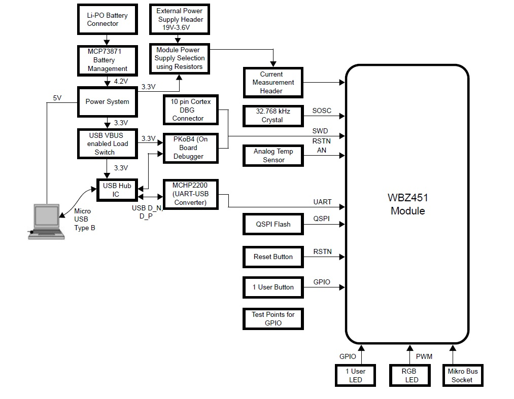
Hardware Block Diagram - Curiosity Board
Hardware Requirement
Table 5-3. Hardware Requirement
Tool
Qty
WBZ451 Curiosity Board(1)
2
Micro USB cable
2
Android/iOS Mobile
1
Amazon Echo Plus(1)
1
Note:
Amazon Echo Plus acts as gateway. If Echo Plus is not available
use the WBZ451 Curiosity board programmed
with “Combined interface” application example as a Gateway.
Microchip Bluetooth Data (MBD) iOS/Android app available in Stores
Alexa App installed on android/iOS mobile phone if Amazon Echo plus is used as
Gateway
Programming the Precompiled Hex File
or Application Example
To run the demo, use a Zigbee network formed by Coordinator/Zigbee Gateway.
Any third-party Gateway like Amazon Echo Plus can also be used as Zigbee Gateway. If
Amazon Echo plus is not available, one of the WBZ451 Curiosity
boards can be programmed with Combined Interface pre-compiled image, which acts as
Zigbee Gateway. Amazon Echo Plus Gateway as well as the WBZ451
Curiosity board based Combined Interface Gateway solutions are explained in the
following demo steps.
To run the demo using Combined Interface as Gateway, two devices are required as
described below:
Combined Interface: One of the
WBZ451 Curiosity boards is programmed with Combined
Interface which can act as Zigbee Gateway/Coordinator. Program the CI pre-compiled
hex image by following the steps mentioned in the “Programming the precompiled hex
file or Application Example” section of the Zigbee Centralized
Network Formation by Combined Interface application, on one curiosity
board.
Combo Light: Another WBZ451 Curiosity board programmed with combo light
application which can act as Zigbee Router. The following steps are for programming
combo light application on another curiosity board.
Programming the .hex File using MPLAB X IPE
Import and program the precompiled
.hex file is located in "<Harmony Content Path>\wireless_apps_pic32cxbz2_wbz45\apps\multiprotocol\ble_zigbee_light_prov\hex"
folder
Open and program the application
example "ble_zigbee_light_prov.X" located in "<Harmony Content Path>\wireless_apps_pic32cxbz2_wbz45\apps\multiprotocol\ble_zigbee_light_prov\firmware"
using MPLAB X IDE
This application demonstrates the multi-protocol (concurrent operation of both Zigbee and BLE
stacks) functionality of PIC32CXBZ2 family of devices
and modules. The Zigbee commissioning over BLE uses Bluetooth Low Energy (BLE) link to
exchange Zigbee commission data and run both Zigbee and BLE tasks simultaneously under
FreeRTOS. The local Zigbee lights (on board RGB LED) can be controlled over BLE or from
Zigbee network. Multi-protocol can also be referred to as "combo" for ease of
readability in this doc.
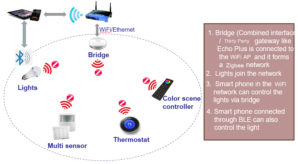
Figure 5-31. Demonstration
Figure 5-32. Demo Application Sequence
Diagram
BLE Light Control (Zigbee Device is not yet Commissioned):
If the combo device is not yet commissioned and
not connected to Zigbee network, still would be able to control the RGB LED through
BLE using BLE Sensor feature of MBD (Microchip Bluetooth Data) mobile
app.
Zigbee Device Commissioning:
By connecting the device to the BLE
Provisioner feature of MBD mobile app, the Zigbee part of combo device can be
commissioned and brought to the existing Zigbee network or can create new Zigbee
network (if there is no nearby network).
Zigbee Local Light Control (Zigbee Device is Commissioned):
Combo light RGB LED can be controlled from Zigbee
Gateway of the same network.
RGB LED can also be controlled through BLE using
BLE Sensor feature of MBD app.
When the light status is changed from BLE, the
light change report will be sent to Zigbee Gateway through Zigbee communication.
When the light status is changed from Zigbee
Gateway through Zigbee communication, the light status will be notified to BLE
Sensor app if it is connected.
Any third-party Gateway like Amazon Echo Plus can also be used as Zigbee Gateway. If Amazon Echo
plus is not available, one of the WBZ451 Curiosity board can be
programmed with Combined Interface pre-compiled image, which acts as Zigbee Gateway. Amazon
Echo Plus Gateway as well as the WBZ451 Curiosity board based
Combined Interface Gateway solutions are explained in the following demo steps.
On-Board Resource Usage
Table 5-4. On-Board Resource Usage
Sensor
Peripheral Used
I/O Pin
Comment
LED Control
TC2 (WO0, WO1), TC3 (WO0) in PWM Mode
PB0, PB3, PB5
RGB LED color control.
Switch
EXTINT0
PB4
SW1 button in curiosity board to do Reset To Factory new
Temperature Sensor
ADC
PB6
Read the room temperature from the MCP9700A sensor available in curiosity board
Timer
RTOS Systick Timer
—
Periodic timer functionality to initiate the sensor read operation and for Adv User LED control
User LED
GPIO
PB7
User LED in curiosity board. To indicate BLE advertisement/connect status
Demo
Steps
Hardware and Software Setup
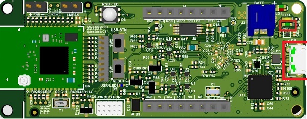
Supply power to the WBZ451 Curiosity board consisting of Combo light application
by connecting a USB cable. Power Supply (PS) Green LED will turn on when connected to
the PC. Figure 5-33. Curiosity Board Power
Supply
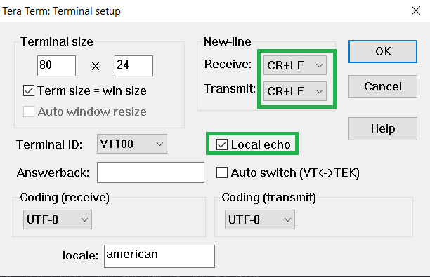
Open TeraTerm and configure as
mentioned below:
Terminal Settings
Baud Rate/Speed –
115200 (as configured in SERCOM configuration)
Parity – None
Data Bits – 8
Stop Bits – 1
Flow Control –
None
For more details on how to set the “Serial Port” and “Speed”, refer to
COM Port Setup
Additionally, local echo and sending line ends
with line feeds shall be enabled in the PC serial terminal application. Figure 5-34. Terminal Setup
Demo Steps: Commissioning
The combo light can be connected to any Zigbee
Gateway.
Discovery of Combo Light from
Amazon Echo Plus: follow this section if Amazon Echo Plus acts as Zigbee
Gateway.
Discovery of Combo Light from the
WBZ451 Combined Interface (CI) gateway: follow
this section if the WBZ451 based Combined Interface acts as
a Gateway.
Discovery of Combo Light from Amazon Echo Plus
Voice Commands: Open Alexa to
discover the Light device. Say Discover my devices or follow the steps
described below.
Alexa App:
Launch Alexa app, from
the menu, select Add Device.
Select the type of smart home
device Light and select Other.
Initiate Discover
Devices
Input command:
resetToFN on light device (Tera Term). The Light will be
discovered and shown as light in Alexa app as illustrated below. Figure 5-35. Discovering
Devices
Note: Echo Plus is in the Discovery mode for 45 secs. Devices
(Lights/other) wanting to join Echo Plus must initiate joining/connecting
procedure within this time limit for a successful connection.
Discovery of Combo Light from the WBZ451 Combined
Interface (CI) Gateway
Supply power to another WBZ451 Curiosity board which is programmed with Combined
Interface image by connecting a USB cable. Power Supply (PS) Green LED will turn ON
when connected to the PC.
Follow Step 2 of Hardware and
Software Setup section for UART terminal Setup
Input command:
resetToFN and look for the below logs for successful Zigbee
network formation on CI Figure 5-36. Tera Term
CI will open up the network for other Zigbee devices to join for first 180 secs
from the first powerON. If commissioning of Combo Light is initiated after this
180 sec, Combo Light will not get joined. This is same as Alexa saying
“Discovering and put the device is pairing mode”. To open up the network after 180
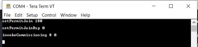
sec, send the below commands in CI, before commissioning is initiated in combo
device.
setPermitJoin
                        180
: This command opens up the network for next 180 sec
invokeCommissioning 8
                        0
: This command opens up the network for "Finding and Binding
procedure"Figure 5-37. Example:
Commands
Connecting Combo Light to Zigbee Gateway (Echo plus or Combined Interface) through BLE
Commissioning
Launch MBD Microchip Bluetooth Data
app from mobile. Open BLE Provisioning feature and scan for the devices.
Look for the device labeled as
“COMBO_LIGHT_XXXX” in the scan results.
Note: “XXXX”
represents a unique number associated with this combo device
Establish a connection with the
device and refer to the subsequent screenshots provided for guidance on the
commissioning process.
Observe that the Blue "User LED" will
be solid ON when device is connected to the mobile app.
Observe that RGB LED will be blinking
when the device joins/forms a network at the interval of 1 sec for next 180 sec. This
indication is required as per Zigbee specification.
Note:
The Combo Light is
configured with default primary channel mask (11,15,20,25) as per Zigbee
specification. The channel configuration from mobile app is needed only when
the Gateway channel is not in any of the default channels.
If commissioning procedure,
does not find the nearby network (for example, Echo Plus), try to find the
channel of the network, and configure the same channel while
commissioning
Figure 5-38. MBD App
Figure 5-39. MBD App
When the Combo Light is joined to an existing network/formed its own network, the
device state can be seen as “Commissioned” as illustarted in the above figure.
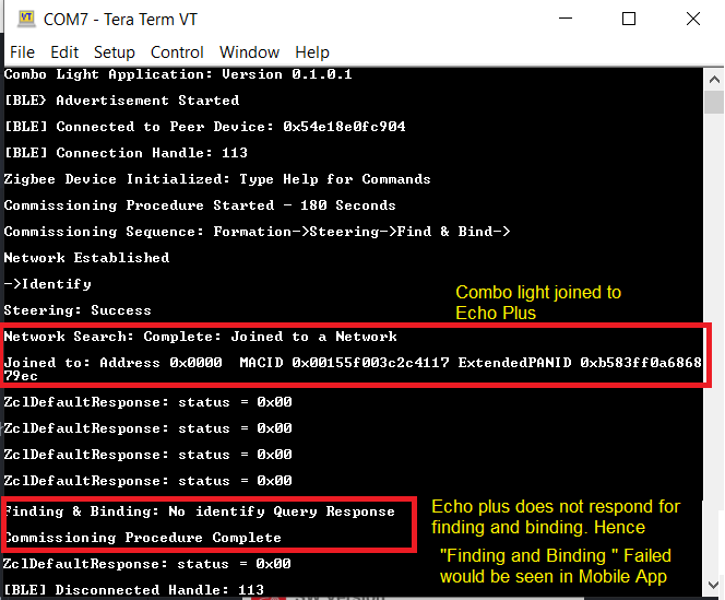
Success log on Combo Light when commissioned with Echo plus
Figure 5-40. Tera Term
Figure 5-41. Alexa
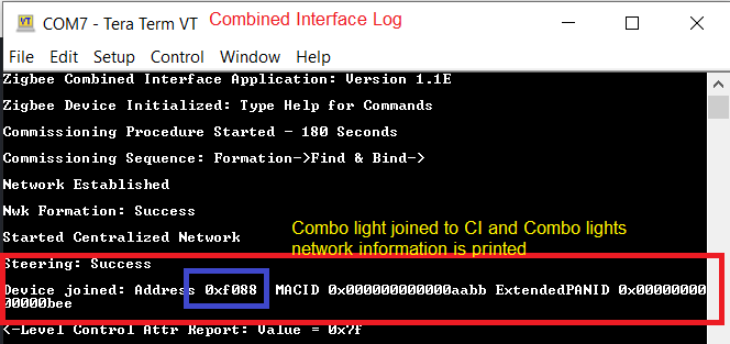
Success log on Combo Light when
commissioned with Combined InterfaceFigure 5-42. Combined Interface
Figure 5-43. Combo Light
Status messages during commissioning:
below status messages can be observed during the commissioning procedure based on the
conditions.
Device Joined to an existing network
Figure 5-44. Joined to
Existing Network
Device formed its own
network.
Figure 5-45. Device Forming New
Network
When the commissioning procedures is initiated, the Combo Device search
for any nearby network to get joined. If it does not find any network, then it
form its own new network, since Zigbee light has the capability of forming its
own distributed network.
Fail Status: commissioning has failed (did not join/create own network)
Figure 5-46. Commissioning
Failed
Other Features in “BLE Provisioner” App
Info page shows some useful information like device type, current channel, device
IEEE address and device state (Commissioned, Not-Commissioned)
Device name can be changed to any user preference name. While the device is
scanned from MBD app, this device name will be seen in the scanned list. The name
can be changed irrespective of commissioning state
Re-Commissioning : If the Combo Light already joined to a network, and wanting to
recommission to new network, the current networking related information to be
deleted from NVM (Nonvolatile memory). Connect the Combo Device from “BLE
Provisioner” feature from MBD app, and press on Factory Reset. This delets
networking information and the device resets. Connect with Combo Light again and
do the commissioning by following the step 3 and 4. Figure 5-47. Factory Reset
Note: If the Combo Light was joined to
an Echo Plus previously, remember to remove the light info from Alexa app before
initiating the recommissioning.
Demo Steps: Light Control
RGB LED on the WBZ451 Curiosity board is tied with Zigbee and BLE functionality. The LED color
and brightness can be changed through Zigbee network as well as from mobile app through
BLE. The RGB color is synced with both Zigbee and BLE network.
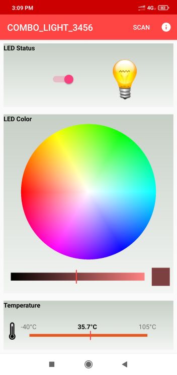
RGB color control from “BLE Sensor”
feature of MBD mobile app
Launch MBD Microchip Bluetooth Data app from mobile.
Open BLE Sensor feature and scan for the devices.
Look for the device labeled as “COMBO_LIGHT_XXXX” in the scan results.
Note: “XXXX” represents a unique number associated with this
combo device
Establish a connection with the device and refer to the subsequent screenshots
provided for guidance on thelight control.
Observe that the Blue "User
LED" will be solid ON when device is connected to mobile app.
The BLE Sensor mobile app will show the temperature (deg C) and LED status
received from device, as well as allows the user to vary the RGB color and
brightness
Figure 5-48. Light Control
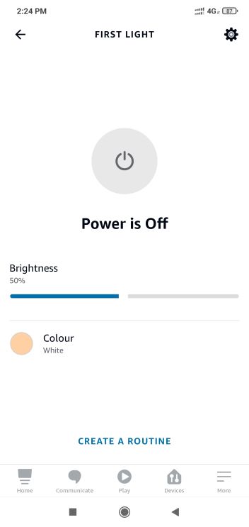
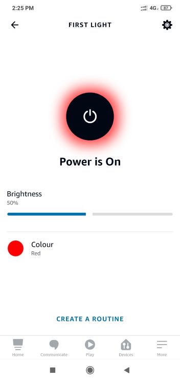
RGB color control from Alexa
Either through voice commands like
"Alexa, Turn on my first light"
"Alexa, Change color of my first light to "GREEN""
"Alexa, increase the brightness of my first light"
or from Alexa app the RGB LED can be controlled through Zigbee
network.
When the color is
changed from Alexa, if combo light is connected with “BLE Sensor”
mobile app, the changed color can be seen in mobile app as well.
If color is changed
from “BLE Sensor” (MBD app), it will be reflected in Alexa app. There
may be delay in syncing, since it depends on read attribute request
from Alexa as explained in the below note and hence, expect max 20 sec
of delay.
Note:
Echo Plus does the Zigbee binding only for ON/OFF and Level Control
Clusters. The color control cluster binding is not done from Echo
Plus. Also, Echo Plus send the configure reporting command to Combo
Light to disable periodic reporting of light attributes. Hence, Combo
Light will not report periodically. Instead Echo plus send the read
attribute command to Combo Light every ~20 sec and get the light
values. Also, the read attribute command for color values will start
only when the first color change is initiated from Alexa. Hence, it is
required to do first color change from Alexa, before changing from BLE
sensor app for color synchronization to take place.
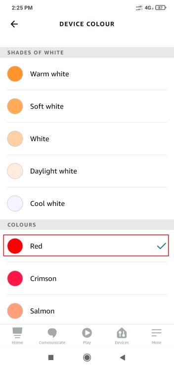
When the LED color is controlled from Alexa, there are two color
control options available. One is temperature color control (“SHADES
of WHITE” in below figure) and another is HueSaturation (colors in
below figure) color control. BLE light is synced only for
HueSaturation color control. So, if the color is changed for
temperature color control, the RGB LED will be changed, but, the
values will not be updated on BLE app.
-->
-->
RGB color control from Combined
Interface
The RGB color can be controlled from Combined Interface through console
commands.
Similar to Alexa, when the RGB color is changed from Combined Interface, will be
reflected in “BLE Sensor” (MBD app) if connected. Changing from "BLE Sensor" app
will be seen in next received report in Combined Interface
The network address of the Combo Light is required to send light control commands
to Combo Light.
This network address can be got
from Combined interface console log while commissioning was done. Figure 5-49. Combined Interface logs
Another way to obtain the
network address in Combo Light side is by executing the below command
Command
← getNetworkAddress
Response
→ f088
Example
←getNetworkAddress
→f088
←onOff 0x0 0xf088 0x23 -on  // Light ON
←onOff 0x0 0xf088 0x23 -off // Light OFF
//0x23 is zigbee end point number used for light can be taken from MCC configurator
Note: 0x45 and 0x67 are the configurable Hue and
Saturation values
Demo Steps: Other Features
On board button actions:
When the on board "User Button (SW2)" is
pressed for more than 10 sec, it deletes all the networking information and
will bring the device to factory default state. GREEN LED will be ON for a
short time to indicate the successful Factory Reset state.
When the on board "User Button (SW2)" is
pressed for more than 5 sec, it starts the commissioning procedure, if not
already commissioned. This is same as “BLE provisioning” mobile app
initiating the commissioning procedure.
Persistent Data Storage (PDS): The RGB light status (ON/OFF) and brightness values
are stored in NVM. So, power OFF/ON of Combo Light, these values persist and RGB
LED will reflect accordingly. This PDS storage is tied to Zigbee network.
Combo device is not yet commissioned: Light values are not stored in NVM in
this scenario. So, power OFF/ON the light values will default to OFF Status
and default color (white, HSV = 0,0x7F, 0x7F)
Combo Device is commissioned: The light ON/OFF status and light brightness
is being stored in non-volatile memory in this case. So, power OFF/ON, the
LED will be updated with light ON/OFF and brightness values retrieved from
previous transaction.
Developing the Application from
Scratch using MCC
The following steps helps to understand the PIC32CXBZ2
device Zigbee and BLE stack programming structure. Recommendation is to follow the
steps. If wish is to have Out-of-Box experience with the precompiled hex file go to the
top of this section.
Note: It is recommended that new users of MCC
to go through the overview.
Import component configuration – This
step helps users setup the basic components and configuration required to develop
this application. The imported file is of format .mc3 and is located
in the path "<Harmony Content Path>\wireless_apps_pic32cxbz2_wbz45\apps\multiprotocol\ble_zigbee_light_prov\firmware\ble_zigbee_light_prov.X".
Note: Import and export functionality of Harmony component
configuration will help users to start from a known working setup of MCC
configuration
Verify the project graph and
configuration options shown in the below steps.
Another method is manually adding and
configuring the components in project graph
From “Device Resources” field,
select + Extended Color Light component (Zigbee component), to add it in
project graph.
Accept Dependencies or
satisfiers, select YesFigure 5-51. Auto-Activation and
Auto-Connection Request
From “Device Resources” field,
select + BLE Stack component, to add it in project graph.
BLE Stack componentFigure 5-52. BLE Stack
Component
From “Device Resources” field,
select Transparent service and profile component, to add it in project
graph.Figure 5-53. Transparent Service
and Profile
Add UART component
needed for console logs and commands. Right click on the yellow triangle on
Extended Color Light component to add satisfiers as illustrated
below. Verify the UART SERCOM configuration as in Zigbee
Console CommandsFigure 5-54. SERCOM0
Add Bootloader Services to the project graph, as illustrated in the following
figureFigure 5-55. Bootloader Services
Add BLE Zigbee Provisioning to the project graph, as illustrated in the
following figureFigure 5-56. BLE Zigbee Provisioning
From “Device Resources” field, select + BLE OTA APP SERVICE component,
to add it in project graph. and accept dependenciesFigure 5-57. BLE OTA APP SERVICE
From “Device Resources” field, select + ADCHS, + DSU, +
EIC, + RCON, + TC2, + TC3, + TCC0 and +
TCC2 components, to add it in project graph.Figure 5-58. Adding Components
Verify if the project graph window
has all the expected components. as illustrated in the following figure:Figure 5-59. Project Graph
Edit APP_TIMER_SERVICE
Configurations
Select APP_TIMER_SERVICE component in project graph, to open component
configuration and configure as illustrated in the following figure
Figure 5-60. APP_TIMER_SERVICE
Edit Device Information Service Configurations
Select Device Information Service component in project graph, to open
component configuration and configure as illustrated in the following figure
Figure 5-61. Device Information Service
Edit Core Configurations
Select Core component in project graph, to open component configuration and
configure as illustrated in the following figure
Figure 5-62. Core
Edit FreeRTOS Configurations
Select FreeRTOS component in project graph, to open component configuration
and configure as illustrated in the following figure
Figure 5-63. FreeRTOS
Edit BLE Stack Specific Configurations
Select BLE Stack component in project graph, to open component
configuration and configure as illustrated in the following figure
Figure 5-64. BLE Stack
Edit Transparent Profile Configurations
Select Transparent Profile component in project graph, to open component
configuration and configure as illustrated in the following figure
Figure 5-65. Transparent Profile
Edit BLE OTA APP SERVICE Configurations
Select BLE OTA APP SERVICE component in project graph, to open component
configuration and configure as illustrated in the following figure
Figure 5-66. BLE OTA APP SERVICE
Edit Zigbee Stack Specific Configurations
Select Extended Color Light component in project graph, to open component
configuration and configure as illustrated in the following figure
Figure 5-67. Extended Color Light
Edit PDS_SubSystem Specific Configurations
Select PDS_SubSystem component in project graph, to open component
configuration and configure as illustrated in the following figure
Figure 5-68. PDS_SubSystem
Edit Peripheral Specific Configurations
Select SERCOM0 component in project graph, to open component configuration
and configure as illustrated in the following figure
Figure 5-69. SERCOM0
Select USART component in project graph and configure as illustrated in the
following figure
Figure 5-70. USART
Select ADCHS component in project graph and configure as illustrated in the
following figure
Figure 5-71. ADCHS
Select TC2 and TC3 (same configuration for both) component in project graph
and configure as illustrated in the following figure
Figure 5-72. TC2 and TC3
Select EIC component in project graph and configure as illustrated in the
following figure
Figure 5-73. EIC
Select TCC0 component in project graph and configure as illustrated in the
following figure
Figure 5-74. TCC0
Select Pin Configuration from project graph and configure as illustrated in
the following figure
Figure 5-75. Pin Configuration
Select System component in project graph and configure PPS Output as
illustrated in the following figure
Figure 5-76. System Configuration
Select Clock Configuration from project graph and configure as illustrated
in the following figure
Files and Routines Automatically
Generated by the MCC
After generating the code from MCC interface by clicking Generate Code, below is the
project folder structure.Figure 5-78. Project Files
BLE, Zigbee Stack Initialization and Application Callback Registration:
The RF System, BLE System, ZIGBEE, PERIPHERAL initialization routine executed during
program initialization can be found in SYS_Initialize() of
initialization.c file.
Zigbee stack provides various APIs for application, and those APIs belong to the
specific module within dedicated group. The sequence of initialization is already taken
care in the stack when Zigbee_Init() from
initialization.c is called.Figure 5-79. initialization.c
The BLE stack initialization routine executed during application initialization can be
found in APP_BleStackInit() in app.c. This call
initializes and configures different BLE layers like GAP, GATT, SMP, L2CAP and BLE
middleware layers and registers the application layer callbacks. The event callbacks
from BLE stack, BLE middleware and profile/service layer are registered.
Also, the MCC configured advertisement data payload can be seen in
APP_BleConfigBasic()Figure 5-80. APP_BleConfigBasic()
Similar to BLE, Zigbee stack also generate events to inform application if there is any
status changed or activity. Application may need to get the relevant information from
Zigbee Stack and do the corresponding procedure.Figure 5-81. app.c
BLE, Zigbee stack application events handling: app.c file is
autogenerated and has a state machine for application callback handling from BLE, Zigbee
stacksFigure 5-82. app.c
User Application Development
Compile MCC Auto-generated Project
Build Project, upon building project user action is required as mentioned User
Action.
Helper Files
This project requires necessary helper files to build and run. The files needed to be
added to the project or manually made. The files required are
app_adv.c, app_ble_sensor.c,
app_button_handler.c, and their respective files and can be found in
the "<Harmony Content Path>\wireless_apps_pic32cxbz2_wbz45\apps\multiprotocol\ble_zigbee_light_prov\firmware\src"folder.
They must be added to the custom project in the same “src” directory.
Files rgb_led.c, temp_sensor.c and their respective
header files are also needed for a proper demo. These files are in a separate directory
named “sensors” located in the "<Harmony Content Path>\wireless_apps_pic32cxbz2_wbz45\apps\multiprotocol\ble_zigbee_light_prov\firmware\src""
folder.
Create a function called
APP_Init() in the app.c file and add the following
code for proper initialization
Figure 5-84. app.c
Call this function in the APP_STATE_INIT case, remove the
APP_BLE_StackInit() function call, and call
APP_Button_Init() as illustrated below:Figure 5-85. app.c
In app.h, add APP_TIMER_ADV_CTRL_MSG,
APP_TIMER_BLE_SENSOR_MSG, APP_MSG_BUTTON_INT,
APP_TIMER_OTA_TIMEOUT_MSG, and APP_TIMER_OTA_REBOOT_MSG to
the APP_MsgId_T struct as illustrated below.Figure 5-86. app.h
Handle these cases in the APP_STATE_SERVICE_TASKS case in
app.c as
follows:
Also in the app_ble_handler.c file, include the library and add the
following code in the APP_BleSmpEvtHandler() function to handle a
failed pairing event as illustrated
below.
Add the following code to
the APP_BleGapConnEvtHandler() function to handle the connected
event
appSnprintf("[BLE] Connected to Peer Device: 0x");
int idx;
for(idx=(GAP_MAX_BD_ADDRESS_LEN-1); idx>=0; idx--)
      appSnprintf("%02x", p_bleConn->connData.remoteAddr.addr[idx]);
appSnprintf("\n\r[BLE] Connection Handle: %d\n\r",p_bleConn->connData.handle);
APP_TIMER_StopTimer(APP_TIMER_ADV_CTRL);
USER_LED_Clear();
Figure 5-97. app_ble_conn_handler.c
Within the same function, APP_BleGapConnEvtHandler(), add the following
code to handle the disconnect event and remove the “BLE_GAP_SetAdvEnable(true,
0);” function
call.
Add the bootloader_timer.X.production.hex file to the loadables in the
project properties. The hex file can be found in "<Harmony Content Path>\wireless_apps_pic32cxbz2_wbz45\apps\multiprotocol\ble_zigbee_light_prov\firmware\ble_zigbee_light_prov.X"folder
Figure 5-100. Project Properties
Configure the SignFirmware in the project properties as illustrated below. The private
key file can be found in "<Harmony Content Path>\wireless_apps_pic32cxbz2_wbz45\apps\multiprotocol\ble_zigbee_light_prov\firmware\ble_zigbee_light_prov.X"folder.Figure 5-101. Project Properties
Extended
Functionalities
This application also implements device firmware over BLE link
(Over-The-Air upgrade) and Serial device firmware upgrade through serial UART
interface
BLE DFU: Refer to the Device firmware update over
BLE section for details on code, configuration and running OTA demo
procedure.
The communication protocol exchange between BLE Provisioning mobile app/ BLE Sensor mobile app
(BLE Central) and the WBZ451 module (BLE peripheral) is
explained in the Zigbee Commissioning through BLE -
Protocol Exchange
section.


 Note: If the Combo Light was joined to an Echo Plus previously, remember to remove the light info from Alexa app before initiating the recommissioning.
 -->
-->


 Note: By default, the coordinator also has the same value. In a network the UID value must be unique


