
3.2.1 BLE Sensor App
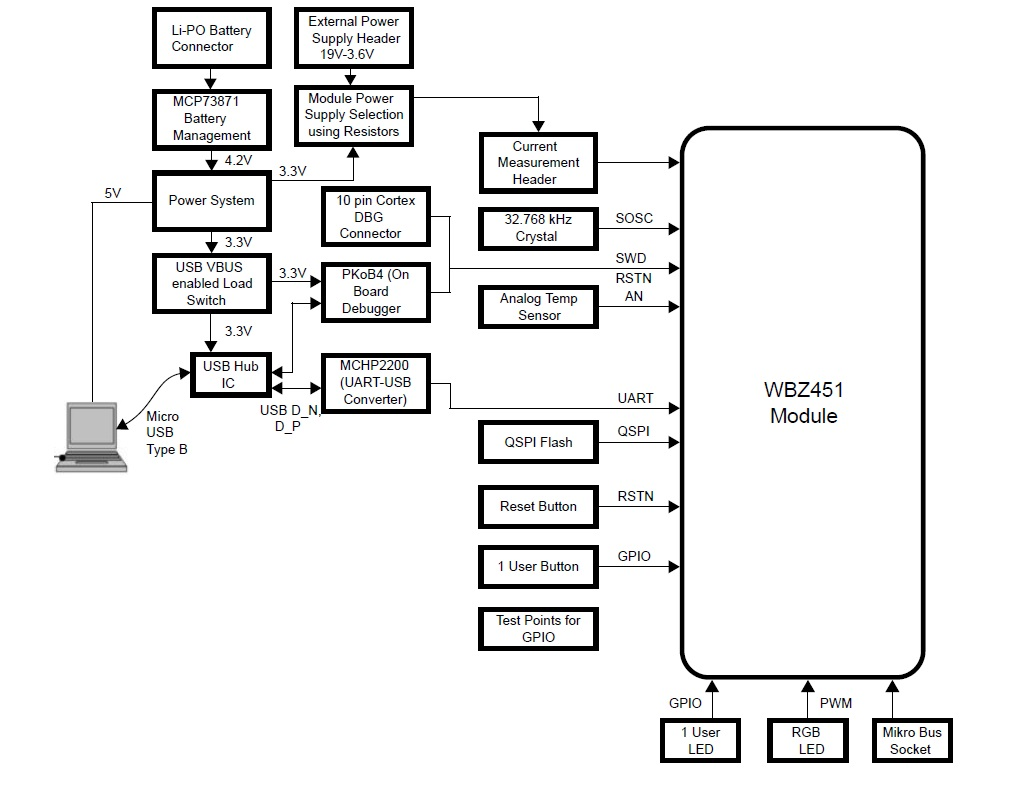
WBZ451 Curiosity Board
Device: PIC32CX1012BZ25048(MCU) on WBZ451 Module
On-Board: Analog Temperature Sensor, RGB LED, User Button, User LED, USB-UART converter

Hardware Requirement
| Tool | Qty |
|---|---|
|
WBZ451 Curiosity Board | 1 |
|
Micro USB cable | 1 |
|
Android/iOS Smartphone | 1 |
Software Requirement
Smart phone App
- Microchip Bluetooth Data (MBD) iOS/Android app available in stores.
Programming the Precompiled Hex File or Application Example
Programming the .hex File using MPLAB X IPE
- Import and program the
precompiled
.hexfile located in"<Harmony Content Path>\wireless_apps_pic32cxbz2_wbz45\apps\ble\advanced_applications\ble_sensor\hex\ble_sensor.X.production.signed.unified_gpiobased.hex"folder - For more details on the steps, go
to Programming A Device Note: Ensure to choose the correct Device and Tool information.
Programming the Application using MPLAB X IDE
- Follow the steps mentioned in Running a Precompiled Example section.
- Open and program the application example “
ble_sensor.X” located in “<Harmony Content Path>\wireless_apps_pic32cxbz2_wbz45\apps\ble\advanced_applications\ble_sensor\firmware\ble_sensor.X” using MPLAB X IDE
For more details on finding the Harmony content path, refer to Installing the MCC Plugin
Demo Description
This application demonstrates the capability of the WBZ451 module to connect to a smart phone through Bluetooth Low Energy (BLE). Once connected, The RGB LED on the Curiosity board can be controlled by mobile app. The WBZ451 device will also report the temperature data to smart phone periodically.
-
The WBZ451 module is a BLE peripheral device advertises on start-up. The user can then initiate the connection through a mobile app. The advertisement payload holds the temperature information and the RGB ON/OFF status.
-
Use the “BLE Sensor” feature from the Microchip Bluetooth Data (MBD) mobile app for BLE demonstration.
- Application is supported by iOS and Android OS
- Available in respective app stores/play stores
-
When connecting/once connected to the application, the user LED turns ON in BLUE
- User LED blinks in 500 ms interval when the device is sending advertisement packets
- User LED turns solid once connection between the WBZ451 module and a smart phone is established
-
From the MBD app, the following actions can be performed
- The RGB LED can be switched ON/OFF
- When LED is switched ON, the
RGB color can change to any color from the mobile app color wheel.
- The RGB color value is received as HSV (Hue, Saturation, Value) from the mobile app through the Transparent Profile and Service (TRPS)
- The HSV value is then converted to RGB equivalent value in the device. The corresponding PWM duty cycle for the RGB is then calculated and provided on RGB LEDs.
-
From the WBZ451 Module, the following actions can be performed:
-
The RGB LED can be switched ON/OFF by pressing the On board "User Configurable Switch"
-
When the User Configurable Switch is pressed and released the RGB LED is switched ON with the default color being GREEN or the last stored color.
-
When the User Configurable Switch is pressed and released again, then the RGB LED is toggled to the previous state.
-
-
The temperature sensor reads the temperature every 1 second and then sends the value to mobile app when the temperature changes by about 1°C
-
Testing
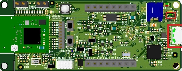
- Power Up: Connect the Curiosity board using Micro USB to PC. Power Supply Green LED will turn on when connected to PC.
- Program the precompiled hex file or application example as mentioned
- UART Console Behavior:
- The application activity is shown in Console Log through on-board UART-USB converter
- Open TeraTerm and configure
as mentioned below:Terminal Settings
- Baud Rate/Speed – 115200 (as configured in SERCOM configuration)
- Parity – None
- Data Bits – 8
- Stop Bits – 1
- Flow Control – None
Note: For more details setting up the “Serial Port” and “Speed”, refer to COM Port Setup section. - Press the Reset Switch on the Curiosity board and console output will be as illustrated below
Figure 3-178. Tera Term Console logs 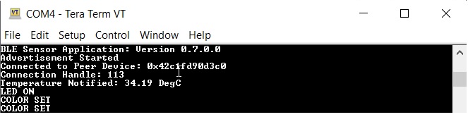
- BLE Connection Behavior:
- Launch the MBD mobile app and
follow the following figures to establish BLE connectionNote: The User LED will be blinking BLUE if BLE connection is not established and will turn solid BLUE once BLE connection is established
Figure 3-179. BLE Sensor Feature 
Figure 3-180. Device Type 
Figure 3-181. Scanning 
Figure 3-182. Devices on Network  Note: In “BLE_SENSOR_XXXX”, ‘XXXX’ is a unique number associated with the board
Figure 3-183. BLE LED Control 
Figure 3-184. Tera Term Logs 
- Launch the MBD mobile app and
follow the following figures to establish BLE connection
The BLE Sensor mobile app shows the LED status and the temperature reading (°C), as well as allow the user to vary the RGB color and brightness
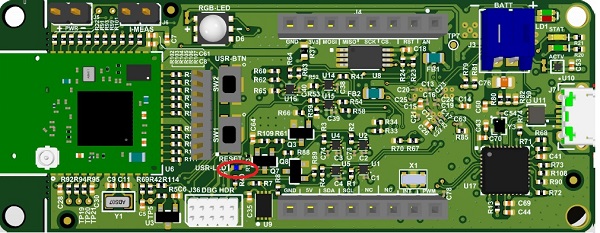
- The RGB LED can also be switched ON/OFF by pressing the On-board User Configurable Switch. The ON/OFF LED status must be reflected on the mobile app as well if connected. When the User Configurable Switch is pressed and released, RGB LED is switched ON. When pressed and released again, the previous state will be toggled.
- Firmware Version
- Bluetooth SIG-defined "Device Info Service" is implemented in the device to share certain information like firmware version, manufacture name, and so on
- Verify the firmware version illustrated in the console with the MBD mobile app
Figure 3-185. Firmware Version 
Figure 3-186. Firmware Version in MBD App 
Figure 3-187. Firmware Version Details in MBD 
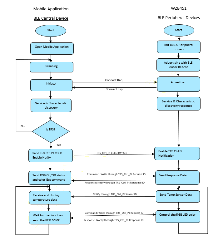
Protocol Exchange
For more details on the communication protocol exchange between BLE Sensor mobile app (BLE central) and the WBZ451 Module (BLE peripheral), refer to the Protocol Exchange section.
Application Flow Diagram
Customizing the Application
The BLE Sensor demo is based on the TRPS request and response. It is not tied only to this specific BLE Sensor application and therefore can be customized as per the users need.

- The protocol parser is
implemented in
app_trps.candapp_trps.h.- Request and Response: when the user wants to get and modify data on the device.
- Notify: when there is a new data to be sent to mobile app.
- The protocol commands are defined
in
app_ble_sensor.hand related sensor functionalities are implemented inapp_ble_sensor.c- Request and Response:
when a command request is received from the mobile app,
app_trps.cparses the data and forwards it to a specific command callback handler inapp_ble_sensor.c - Notify: when a specific
Sensor data is sent to the mobile app,
app_ble_sensor.cplaces the data in data base and calls for the notify handler inapp_trps.c(APP_TRPS_SendNotification())
- Request and Response:
when a command request is received from the mobile app,
Example: To add a command to get the temperature in Fahrenheit.
Complete the SDK Setup, open and program the
application example "ble_sensor.X" located in "<Harmony Content Path>\wireless_apps_pic32cxbz2_wbz45\apps\ble\advanced_applications\ble_sensor\firmware\ble_sensor.X
using MPLAB X IDE.
-
Changes to –
app_ble_sensor.h- Define the following
- a new control command ID to 0x14
- a new control command response
- length for the new response command
- Inside the existing
APP_TRPS_SensorData_Tstructure, add a new data structure with “msb” and “lsb” members which will hold the response data to be used for conversion - Increase the list size
BLE_SENSOR_CMD_RESP_LST_SIZEby one. - Add the new command request/response set in
BLE_SENSOR_DEFINE_CTRL_CMD_RESP()list
- Define the following
-
Changes to –
app_ble_sensor.c- To read the temperature periodically and store in the newly defined data
structure, add the below code in
APP_TRPS_Sensor_TimerHandler()Figure 3-189. app_ble_sensor.c
- After doing the above changes, select option Build Main Project in
the IDE to compile the application example.
Figure 3-190. Build Main Project 
- Then, select option Run
Main Project in the IDE to program the target, the On-board debugger
will program the example application
Figure 3-191. Run Main Project 
- To read the temperature periodically and store in the newly defined data
structure, add the below code in
- Testing with the MBD mobile appThe “BLE Sensor” feature in the MBD mobile app is designed to only work with specific functionalities. So, if new commands are added in the BLE Sensor application, the BLE Sensor mobile app will not know about it. To test the newly added code above, the “BLE Smart” feature in the MBD can be used. Follow the following figures after launching the MBD mobile app.
Figure 3-192. BLE Smart Feature 
Figure 3-193. BLE Devices in Range 
Figure 3-194. Connection 
Figure 3-195. Microchip Data Service 
Figure 3-196. Microchip Control Characteristic 
Figure 3-197. Enable Notify/Indicate 
Figure 3-198. BLE Write 
Figure 3-199. BLE Read Enable Notify/Indicate 
Figure 3-200. Temperature Notification Logs 
Figure 3-201. Temperature Notification Logs 
Using the MCC
MPLABX Harmony provides the MPLAB® Code Configurator (MCC) tool, a set of modular device and middleware libraries, and numerous example applications, all of which are designed to help developers quickly and easily develop powerful and efficient embedded software. MCC is a free graphical programming environment that generates seamless, easy-to-understand C code to insert into your project. Using an intuitive interface, it enables and configures a rich set of peripherals and functions specific to your application. The following steps can be followed to open MCC tool and generate the code.
- Open the MCC tool from MPLABX
Figure 3-202. MCC 
- Once the MCC tool is launched, the "Project
Graph" shows the list of MCC components used in the specified project.
Figure 3-203. Project Graph 
- Clicking on the specific component block will
allow to change the configuration of that component. (for example, SERCOM0 is
illustrated in the following figure)
Figure 3-204. Component Configuration 
- New components can also be added to the Project
Graph by clicking on the “+” sign next to the peripheral in Device Resources. Then,
configure the component as in step 3. (for example, SERCOM1 can be added into the
Project Graph)

- Once all the required components and
configurations are done, generate the code .
For more details on generating the code, refer to the MPLAB Code Configurator(MCC) Code Generation section.
.Figure 3-205. Code Generation 