3.5 Echo Process
The transmitted ultrasonic waves will propagate in the air until meeting obstacles and reflecting back. Once reflected back to the transceiver, the echo signal will be amplified and filtered in the isolator and pre-amplifier circuit. The signal will then be digitized by the AC with the threshold set up in the firmware. For detailed algorithm, read the firmware user guide available at start.atmel.com.
The echo process circuit mainly includes two parts; a pre-amplifier based on BJT and a 2-stages 4-order band pass filter.
As shown in the figure above, the gain for the pre-amplifier based on BJT is approximately 2.5. This circuit also protects the system from high-voltage impacts from the bursted transceiver.
As shown in the figure above, this filter is a 2-stages 4-order band pass filter with over 600V/V voltage gain. The center frequency is designed to be 40kHz with 10kHz pass-band bandwidth. Also, a DC voltage reference (Vref = 1.65V) is used to provide an offset voltage for the filter to make the signal amplitude as large as possible.
A curve based on measured data for the band pass filter is shown in the figure below. The component tolerances in the design are E24 (5%) for resistors and E12 (10%) for capacitors.
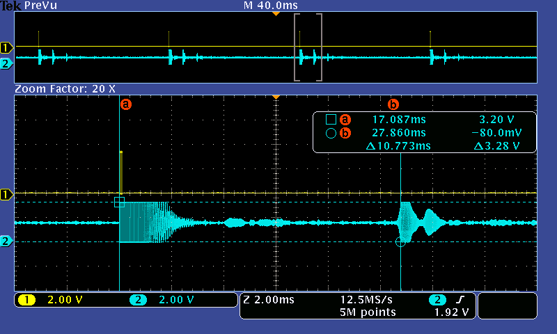
An oscilloscope screen of the ultrasonic echo signal is shown in the figure below.

