The following picture shows the PIC32CXMTG-EK board connected with PL460-EK expansion
board:
Figure 1-49. PIC32CXMTG-EK + PL460-EK
PL460-EK is connected to XPRO Interface connector (J10) of PIC32CXMTG-EK. A 15V DC jack
must be plugged into PL460-EK in order to supply the power for PLC transmission. For
more information about PL460-EK refer to its user guide.
The USB connector (J4) of PIC32CXMTG-EK can be used to:
See Application information
messages on Console. UART baud-rate is configured at 115200 bps (it cannot be
higher due to hardware limitations on this board).
Flash/debug the PIC32CXMTG device with the on-board Jlink debugger
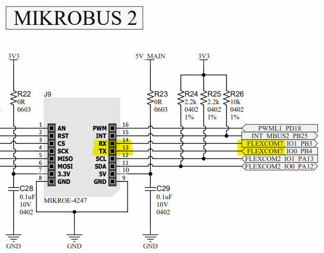
The Host Interface connection is done through mikroBUS 2 connetor, where USART7 is
mapped:Figure 1-50. MikroBUS 2 USART7
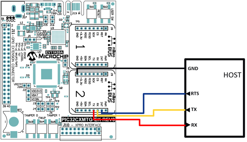
INT pint is used to connect RTS signal from Host, which is required by Host Interface
specification. The following figure shows the connection between Modem and Host:Figure 1-51. Modem To Host Connection
For more information about PIC32CXMTG-EK refer to its user guide.