
1.10.4 Build and Program
The bootloader is a project not generated with MCC. Open it in MPLAB X IDE and build it.
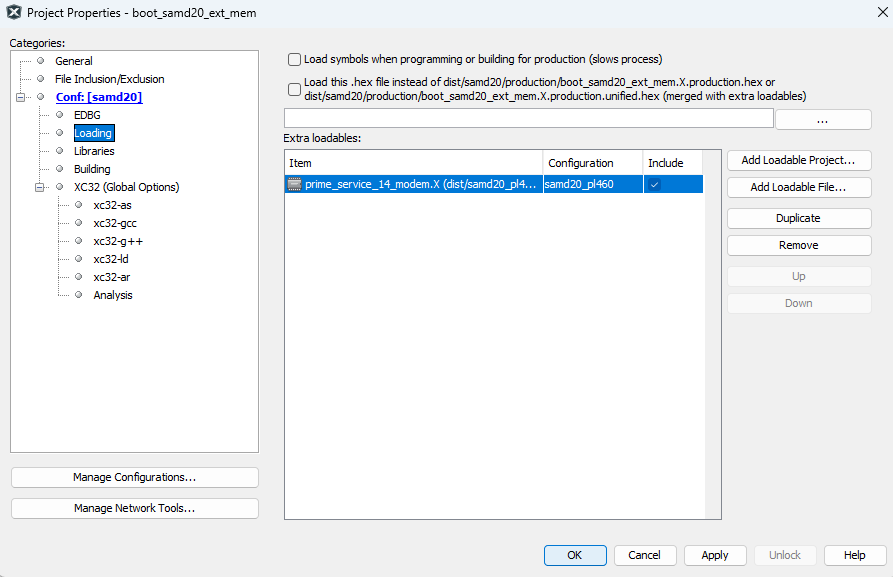
The bootloader project programs the modem application. It lists the modem application as
an extra loadable (Project Properties>Conf: [samd20]>Loading>Extra
loadables). Building and programming the bootloader project with the on-board
debugger therefore writes both binaries — the bootloader and the application — to the
SAMD20 internal Flash in a single operation. The bootloader occupies the first 8 KB
(protected by the BOOTPROT fuse), and the application starts at offset
0x2000.
The PL460 PHY binary is not part of these two images. It is stored in the external SST26
serial Flash and loaded at start-up by the application. The on-board debugger does not
write the external memory, so the PHY binary must be provisioned separately. The first
time, it is sent from a PC with the PRIME_H3_SAMD20_Memory_Tool over
the serial interface (see UART Recovery Mode).
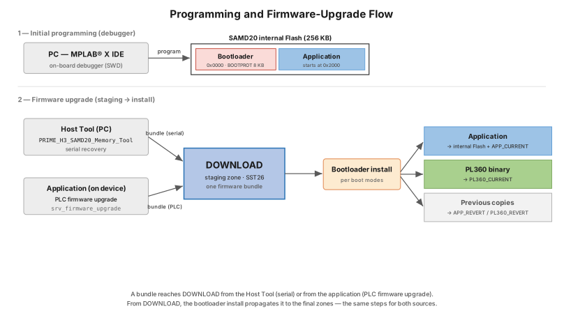
Every image written to the external memory first passes through the DOWNLOAD staging
zone. A bundle reaches the DOWNLOAD zone in one of two ways: from the application during
a PRIME firmware upgrade over PLC (through the srv_firmware_upgrade
service) or from the PRIME_H3_SAMD20_Memory_Tool over the serial
interface. In both cases, the bootloader installs the bundle into the final zones
according to the Boot modes described in Firmware Upgrade Flow; the memory maps
are described in Memory Allocation.
The following figure shows both paths.
Programming a New Board
A factory-fresh board has an empty external SST26 serial Flash, so the PL460 PHY binary must be provisioned before the application can run. The first-time sequence is shown in the following figure.
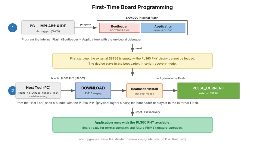
- Program the bootloader and the application into the SAMD20 internal Flash with the on-board debugger (a single build-and-program of the bootloader project, as described above).
- On the first start-up, the SST26 does not yet contain the PL460 PHY binary, so the PHY layer cannot be loaded. The device therefore remains in the bootloader in Serial Recovery mode.
- From the
PRIME_H3_SAMD20_Memory_Toolon the PC, send a bundle that contains the PL460 PHY binary (an image of type'PLCC'). It is staged in the DOWNLOAD zone, and the bootloader installs it into the PL360_CURRENT zone of the external SST26 serial Flash. - The bootloader exits recovery and resets. The application starts with the PL460 PHY layer available, and the board is ready for normal operation and for later PRIME firmware upgrades.
Erase All Before
                    Programming
in the programmer options and set the programming range to
0x000000–0x3FEFF. A full chip erase of the
internal Flash wipes this emulated EEPROM. The boot-mode record is not affected, as
it resides in the BOOT_FLAG sector of the external SST26 serial Flash.