
1.7.1 MCC Project Configuration
The following figure shows the MCC project graph of the PRIME 1.4 Service Modem application for SAMD20 Xplained Pro.
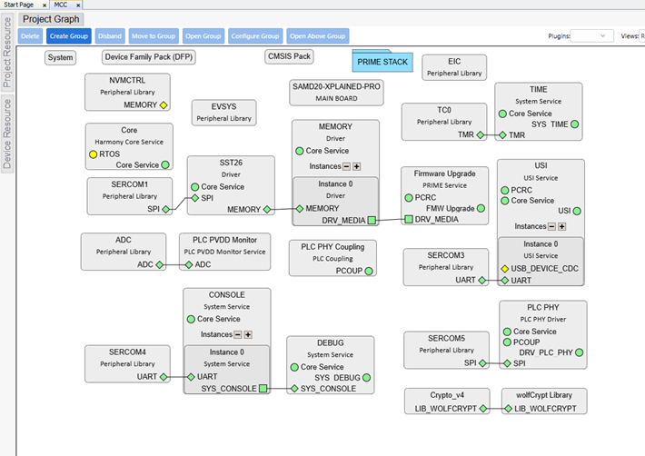
The project is generated with the smartenergy_prime configurator and
includes the PRIME stack and the services required by a Service Node modem. The common
component setup is the same as in the PRIME Service Dual
Modem. The following section describes what is specific to the SAMD20
build.
PRIME Stack Configuration
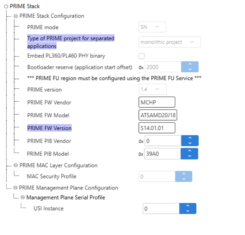
The PRIME Stack is configured as a Service Node with a monolithic project, which is
the only configuration supported on the SAMD20. As shown in the following figure,
the PRIME mode and the type of PRIME project are fixed, the Embed
PL360/PL460 PHY binary option is disabled (the binary is loaded from
external memory) and the Bootloader reserve is set to
0x2000.
PRIME PAL Configuration
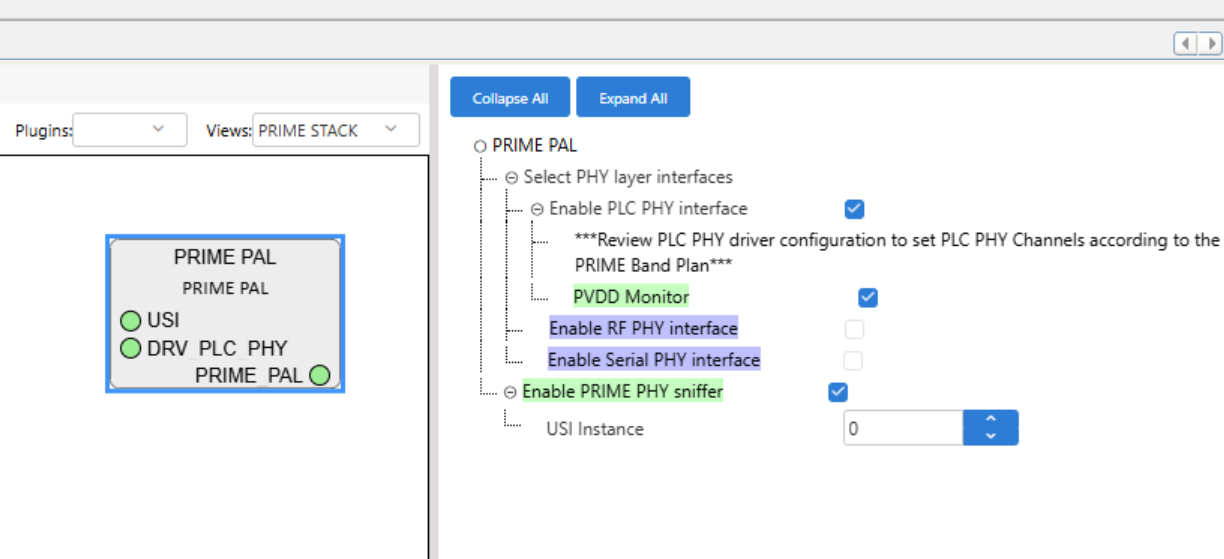
In the PRIME PAL, only the PLC PHY interface is enabled, with the PVDD Monitor enabled. The RF PHY and Serial PHY interfaces are not enabled (this is a PLC-only modem). The PRIME PHY sniffer is enabled and the USI instance is 0. The PL460 PHY binary is not embedded in the application image; instead, the PAL loads it at start-up from the external serial Flash managed by the bootloader (see PRIME Bootloader (External Memory)).
PLC PHY Driver Configuration
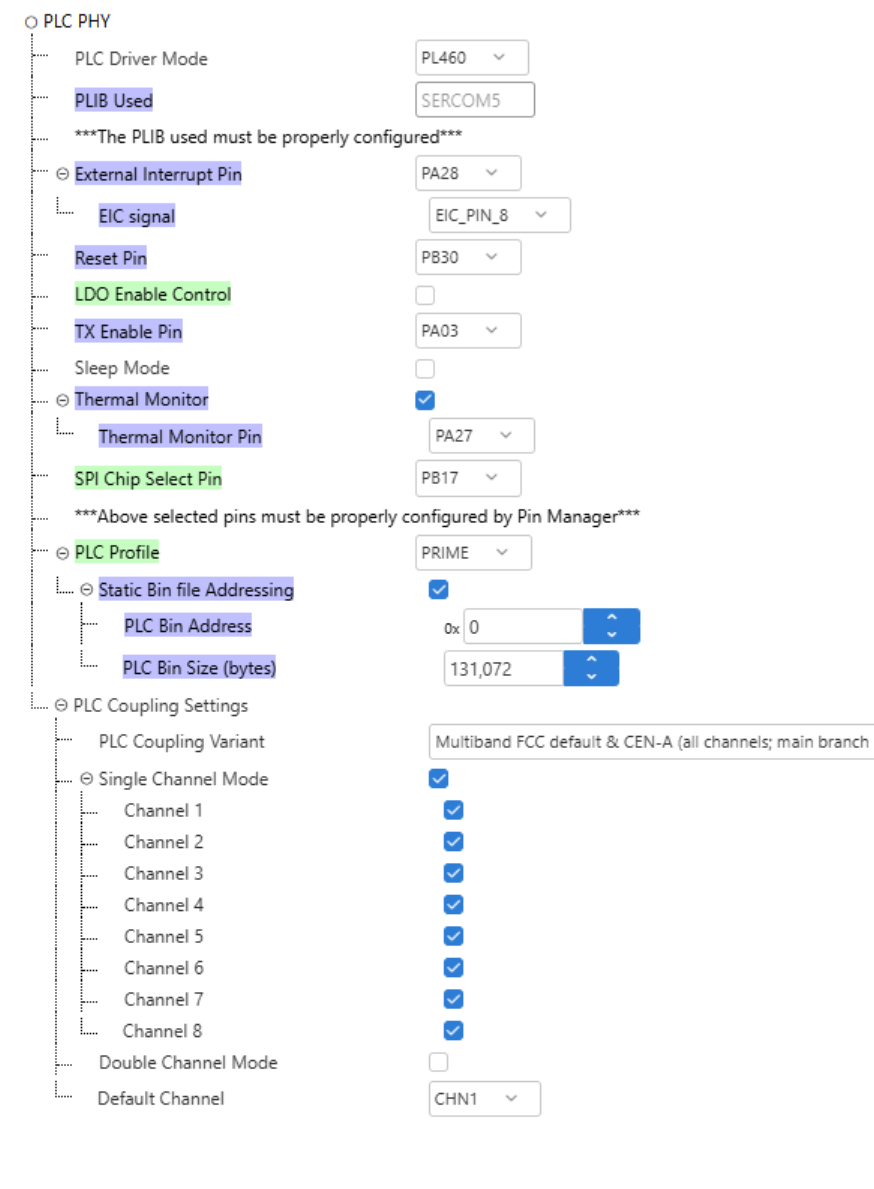
The PLC PHY driver is configured for the PL460 over SERCOM5, with the PRIME profile and the default PL460-EK coupling (Multiband FCC + CENELEC-A). The Thermal Monitor is enabled.
The setting specific to the SAMD20 build is Static Bin file
Addressing, which is enabled. It instructs the driver not to embed the
PL460 binary in the application image. Instead, the binary is provided from external
memory: the bootloader stores it in the external serial Flash and loads it into the
PL460 at start-up (see PRIME Bootloader (External Memory)). Because the binary is supplied this way, the PLC Bin
Address (0x0) and PLC Bin Size
(131072 bytes) fields under Static Bin file
Addressing are not used in this configuration.
Board Component — SAMD20 Xplained Pro
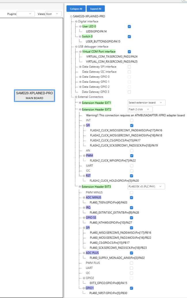
The SAMD20 Xplained Pro board component defines the board capabilities. For this application it enables the on-board User LED 0 (PA14) and the SW0 push button (USER_BUTTON0, PA15), and the USB Virtual COM port interface (on SERCOM3, used by the USI). The FLASH 2 Click board™ that carries the external SST26 serial Flash is selected on the EXT2 connector (SPI on SERCOM1, with the CS, WP, and HOLD lines as GPIO; it requires the ATMBUSADAPTER-XPRO adapter) and the PL460-EK (PLC PHY) is selected on the EXT3 connector (SPI on SERCOM5, plus the ADC input used by the PVDD Monitor).
Additional Components
The following components are configured specifically for the SAMD20 build:
- SERCOM5 in SPI mode drives the PL460 (PLC PHY driver) on the EXT3 connector.
- SERCOM1 in SPI mode drives the
external SST26 serial Flash (DRV_MEMORY) on the EXT2 connector, with the
chip-select, write-protect and hold lines driven as GPIO. It is configured as
SPI host at 1 MHz, 8-bit character size, SPI mode 0.
Figure 1-106. SERCOM1 SPI Configuration (External SST26 Serial Flash) 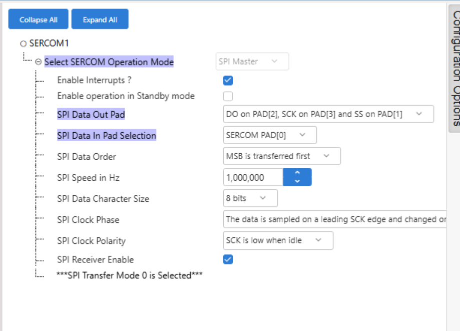
- SERCOM3 in USART mode is used by
the USI service (over the USB Virtual COM port), at 115200 bps, 8 data bits, no
parity, 1 stop bit. It runs in Ring-buffer mode with a 256-byte TX buffer and a
128-byte RX buffer. These ring buffers are kept small to save RAM on the
memory-constrained SAMD20.
Figure 1-107. USI (SERCOM3) Configuration 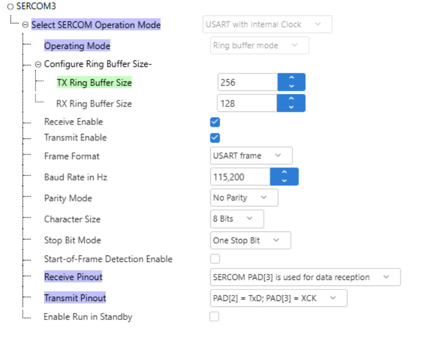
- SERCOM4 in USART mode is used by the Console and Debug services.
- SRV_STORAGE configured over the NVMCTRL emulated EEPROM, because the SAMD20 has no hardware backup registers (GPBR). No MCC configuration is required for this component.
- Firmware Upgrade service is
configured with an external memory backend on the external serial Flash. The
Firmware Upgrade Region Sizeis0x80000(512 KB), the write and read buffers are 256 bytes, and theExternal bootloader FU profileis enabled.Figure 1-108. Firmware Upgrade Configuration (External Bootloader Profile) 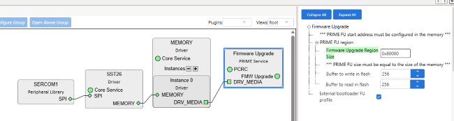
- Crypto (wolfCrypt): the firmware-upgrade signature is verified in software, because the SAMD20 has no hardware crypto engine.
gDrvMemory0EraseBuffer, sized
DRV_SST26_ERASE_BUFFER_SIZE = 4 KB) is regenerated at its full
size by MCC on every regeneration. The PRIME 1.4 Service Modem only issues plain
erase and write operations (never a read-modify-write erase), so this buffer is
unused. To recover the 4 KB of RAM, edit initialization.c after
each regeneration and set the buffer back to 4
bytes:static uint8_t gDrvMemory0EraseBuffer[4] CACHE_ALIGN;