
1.2.5.8.4 Ethernet PHY Porting
This document briefly explains how to add a new PHY to the Microchip Harmony3 TCP/IP stack.
| Table of Contents |
|---|
| Supported PHYs |
| Hardware System Diagram |
| Software Interface |
Supported PHYs
Currently supported PHYs and switches:
- Microchip:
- KSZ8041, KSZ8061, KSZ8081, KSZ8091, KSZ8863, KSZ9031, KSZ9131
- LAN 8700, LAN 8720, LAN 8740, LAN 8742, LAN 8770, LAN 8840, LAN 9303, LAN 9354
- VSC 8540
- A dummy PHY driver used when the PHY does not need software configuration.
- National Instruments:
- DP83640, DP83848
- IC Plus:
- IP101
- The list will expand with the addition of newly supported PHYs.
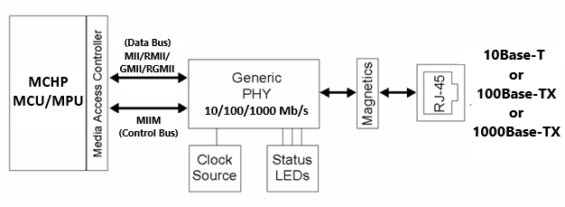
Hardware System Diagram
Software Interface
The Microchip MCU/MPU families of devices with embedded Ethernet controller have support for external MII/RMII/RGMII connected PHYs.
Control and access to the external PHY registers is done using a default MIIM driver that’s part of the Harmony3 framework. This driver uses the standard MIIM control interface that connects an Ethernet Controller with the external PHY.
The Harmony3 PHY driver consists of 2 modules:
- The main/base PHY driver which uses standard IEEE PHY registers.
- The Harmony3 TCP/IP stack provides a default PHY driver object (DRV_ETHPHY_OBJECT_BASE), based on the ‘IEEE 802.3 Clause 22’ standard which all the PHYs are requested to support.
- Normally this driver object should be used as it is and does not need to be touched (Note1).
- The vendor specific functionality
- For providing access to the vendor specific features a DRV_ETHPHY_OBJECT is defined (see “Harmony3 Install Path\net\driver\ethphy\ethphy.h”).
- This object declares a few functions and constants that need to be implemented when adding support for a new PHY.
(I) How to Add a New PHY
A new DRV_ETHPHY_OBJECT needs to be developed, to provide access to the vendor specific features for a new PHY.
Let’s call this new PHY object MY_NEW_PHY_OBJ, for example.
The DRV_ETHPHY_OBJECT definition shows the functions that it needs to provide (see “<Harmony3 Install Path>\net\driver\ethphy\ethphy.h” for details and a complete explanation of the data structure members in the Harmony3 network documentation).
We write our new PHY driver object as follows:
const DRV_ETHPHY_OBJECT  MY_NEW_PHY_OBJ  =
{
    .miiConfigure = my_MIIConfigure,        // function to configure the operation mode:
                                            // MII/RMII/GMII, etc.
    .mdixConfigure = my_MDIXConfigure,      // function to configure the MDIX mode
    .smiClockGet = my_SMIClockGet,          // function to get the SMI clock rate
    .wolConfigure = NULL,                   // no WOL functionality implemented yet
    .phyDetect =  myPhyDetect,              // special/standard detection function
    .bmconDetectMask = myDetectMask,        // special/standard detection mask
    .bmstatCpblMask = myCpblMask,           // special/standard capabilities mask
};
We’ll provide a brief explanation for each member of this data structure.
- DRV_ETHPHY_RESULT my_MIIConfigure ( const struct DRV_ETHPHY_OBJECT_BASE_TYPE*
pBaseObj, DRV_HANDLE handle, DRV_ETHPHY_CONFIG_FLAGS cFlags );
- This function needs to configure the Ethernet PHY in one of the MII/RMII/GMII/RGMII operation modes.
- DRV_ETHPHY_RESULT my_MDIXConfigure( const struct DRV_ETHPHY_OBJECT_BASE_TYPE*
pBaseObj, DRV_HANDLE handle, TCPIP_ETH_OPEN_FLAGS oFlags );
- This function needs to configure the MDIX mode for the Ethernet PHY: Auto, Normal, or Swap.
- unsigned int my_SMIClockGet ( const struct DRV_ETHPHY_OBJECT_BASE_TYPE* pBaseObj,
DRV_HANDLE handle );
- This function should return the SMI/MIIM maximum clock speed of the Ethernet PHY, in Hz.
- DRV_ETHPHY_RESULT myPhyDetect ( const struct DRV_ETHPHY_OBJECT_BASE_TYPE*
pBaseObj, DRV_HANDLE handle);
- This (optional) function should detect that the PHY is present and the communication works as expected.
- If it is NULL (default) then the standard detection procedure will be performed (part of the standard PHY base driver).
- If the PHY requires special handling of the detection, a custom function could be provided.
- uint16_t myDetectMask;
- Optional detect mask to be used by the detection procedure (read/write bits in the BMCON that can be manipulated).
- If 0, then a default mask of BMCON_LOOPBACK_MASK | BMCON_DUPLEX_MASK BMCON will be used.
- PHY drivers that need special processing can use their own detection mask for the default detection procedure or use a specific detect procedure.
- uint16_t myCpblMask;
- Optional extra capability mask to be used by the PHY setup procedure.
- Some PHYs need to be able to use extra bits set if their BMSTAT register doesn't advertise the standard capabilities.
- By default, this value should be 0.
(II) How to use the new PHY Object
The address of this new DRV_ETHPHY_OBJECTobject should be passed to the PHY Initialization Data structure DRV_ETHPHY_INIT:: pPhyObject (usually in initialization.c for a standard Harmony3 networking project).
As an example, the Harmony3 project Ethernet initialization data should look similar to this (only this specific member is detailed here. For other details see the Harmony3 network documentation):
/*** ETH PHY Initialization Data ***/
const DRV_ETHPHY_INIT NEWPHY_InitData =
{
    .ethphyId                = GMAC_BASE_ADDRESS,
    .phyAddress              = 0,
    .phyFlags                = DRV_ETHPHY_CFG_RMII,
    .pPhyObject              = & MY_NEW_PHY_OBJ,
    .resetFunction           = NULL,
    .ethphyTmo               = &drvTmo,
    .pMiimObject             = &DRV_MIIM_OBJECT_BASE_Default,
    .pMiimInit               = &drvMiimInitData,
    .miimIndex               = 0,
};
(III) PHY Object Implementation
A good place to start is by looking at the implementation of an existing DRV_ETHPHY_OBJECT and using it as a model. Look into the “Harmony3 Install Path\net\driver\ethphy\src\dynamic” for examples.
Follow the same approach as outlined in the examples.
drv_extphy_lan8700.c, drv_extphy_lan8720.c, drv_extphy_lan8740.c, etc. are good examples to start with.
(IV) Implementation Details
The implementation of the DRV_ETHPHY_OBJECTdriver object relies on the vendor access functions presented by the base object: DRV_ETHPHY_OBJECT_BASE.
After the communication to the PHY has been established the main base PHY driver will call the vendor PHY object functions to continue its initialization. The vendor PHY functions can use all the base object vendor specific functions to store/retrieve specific data or start SMI transactions.
Currently the supported base objects that the vendor PHY object can use are:
- DRV_ETHPHY_VendorDataSet() and DRV_ETHPHY_VendorDataGet()
- For setting and retrieving custom data needed to implement the functionality.
- DRV_ETHPHY_VendorSMIReadStart() and DRV_ETHPHY_VendorSMIReadResultGet()
- For initiating a PHY register read transaction and getting the result.
- DRV_ETHPHY_VendorSMIWriteStart() and DRV_ETHPHY_VendorSMIWriteWaitComplete()
- To start a PHY write register operation and optionally to wait for it to complete.
- DRV_ETHPHY_VendorSMIOperationIsComplete()
- To check if a new SMI operation can start or if a previous one is still ongoing.
Important Note:
The functions of the DRV_ETHPHY_OBJECTshould not block but return DRV_ETHPHY_RES_PENDING if waiting for SMI transactions!
This is why functions like DRV_ETHPHY_VendorDataSet() and DRV_ETHPHY_VendorDataGet() are provided, for implementation of state machines in functions that need to return a result without waiting for a hardware operation to complete.
Additional Notes:
- The DRV_ETHPHY_OBJECT_BASE is also a virtual object that needs to provide specific
functionality. It can be updated or new PHY base objects could be created as needed. One
situation is for certain switches that have multiple ports and need specific
implementation functions.
- Examples are in the drv_extphy_ksz8863.c, drv_extphy_lan9303.c, drv_extphy_lan9354.c