
3.3 User Guide
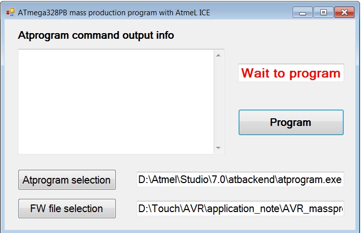
This application note provides an example ATmega328PB production programming software tool as shown in the figure below. When the users click the "Program" button in the programming tool GUI window, it will perform the device programming and output success or fail information after the programming operation has finished. Once the programming is successful, LED0 will switch ON when the users press the SW0 button of the ATmega328PB Xplained Mini Kit and OFF when the SW0 button is released.
The detailed steps on how to use this tool are listed below:
- Step 1: Download the AVR_massproduction_programming_tool_with_atmelice.zip file from the Microchip website and unzip it. After unzipping, it will have two folders; one is the Mass_production_programming_tool and the other is atprogram_example_application_project. In the mass_production_programming_tool directory, you will find the tool application and example firmware image file Button_led.hex, which can run on the ATmega328PB Xplained Mini Kit. The atprogram_example_application_project directory contains the source project developed with Visual C# 2010 Express.
- Step 2: Connect the Atmel-ICE kit to
the ISP programming port of the ATmega328PB Xplained Mini Kit with a 6-pin 100-mil
IDC flat cable as shown in the figure below.
Figure 3-3. ATmega328PB Xplained Mini Kit's ISP Connection with Atmel-ICE 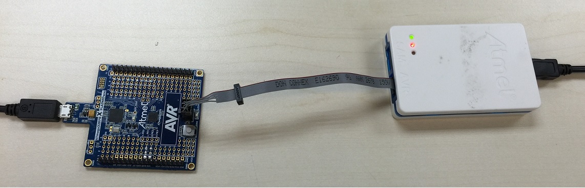
- Step 3: Plug the Atmel-ICE kit's USB cable into the PC and launch the mass_production_programming \Atprogram_application_example.exe application from the directory where you unzip the AVR_massproduction_programming_tool_with_Atmelice.zip file.
- Step 4: Click the "Atprogram selection" button in the programming GUI window and choose the Studio command line utility "atprogram.exe" file path. The atprogram.exe is located in the Atmel Studio installation directory \atbackend.
- Step 5: Click the "FW file selection" button in the programming GUI window and choose the "Button_Led.hex" file from the directory where you unzip the AVR_massprodcution_programming_tool_with_Atmelice.zip file.
- Step 6: Click the "Program" button.
The "programming" string in program_status textbox will show up, as shown in the
figure below.
Figure 3-4. ATmega328PB Chip In-programming Status Display 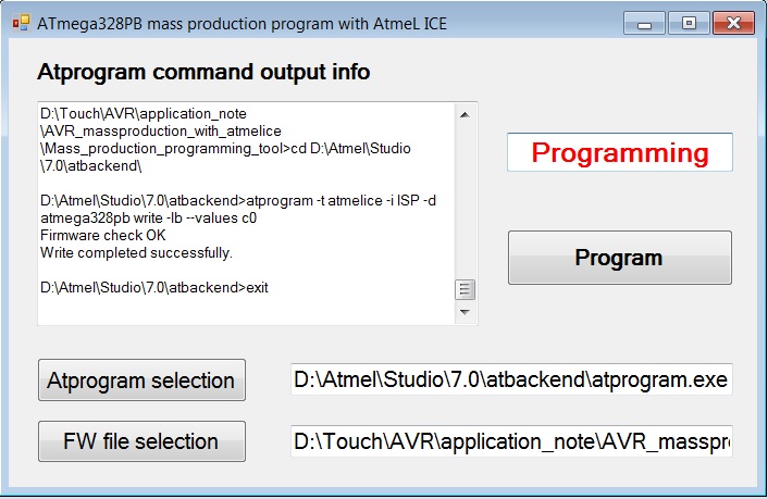
- Step 7: Once programming is finished,
it will show either the "success" string, as shown in figure ATmega328PB chip programming success info
display, or the "fail" string, as shown in figure ATmega328PB chip programming failure info
display, in the program_status textbox. If device programming fails, the
users must first check the connection between Atmel-ICE and ATmega328PB Xplained
Mini Kit's ISP programming connector; secondly, the users must check the ATmega328PB
chip in the ISP programming mode because the kit programming mode may be changed
from default ISP mode to debugWire mode. For ATmega328PB chip programming mode
selection, refer to the AN42469: ATmega328PB Xplained Mini kit
user guide.
Figure 3-5. ATmega328PB Chip Programming Success Info Display 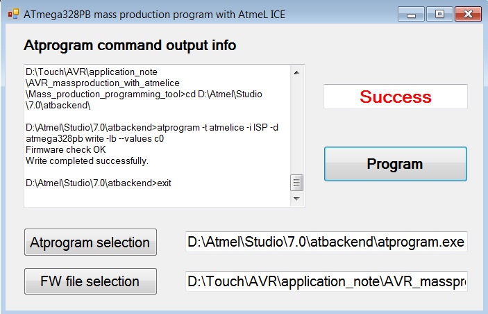
Figure 3-6. ATmega328PB Chip Programming Failure Info Display 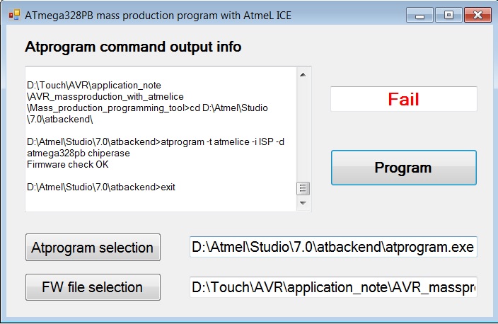
- Step 8: Verify if the example firmware image Button_led.hex is programmed successfully into the ATmega328PB Xplained Mini kit. Once successfully programmed, LED0 will be ON when the SW0 mechanical button is pressed and OFF when the SW0 button is released.