1.2 Connecting Atmel AVRISP mkII
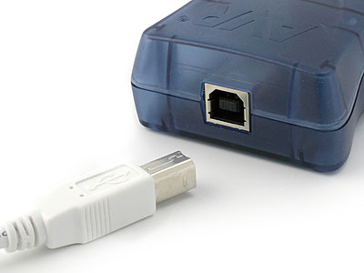
This section describes how to connect the Atmel AVRISP mkII to the host PC and the target device for correct operation. Note that Atmel Studio and the USB driver must be installed. See the Atmel Studio documentation for help. AVRISP mkII must be connected to the computer before connecting it to the target device.

When the AVRISP mkII is connected to the PC, and if the USB driver is installed, the green LED inside the AVRISP mkII close to the USB connector will be lit. The main status LED will be red before the target is detected.
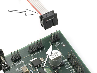
After the AVRISP mkII is connected to the PC, it can be connected to the target. The red stripe on the target cable marks pin 1, and this should be mated with pin 1 on the ISP, PDI, or TPI connector on the target board. See Target Interface for a comparison of the different interfaces.

The AVRISP mkII does not provide power on the VCC pin, but uses this pin to sense the voltage on the target circuitry. Your circuit needs to be powered by external means to operate.
When the AVRISP mkII is connected to both the PC and the target board the main status LED should be green indicating that target power has been detected. AVRISP mkII is now ready to be used with Atmel Studio or the programming command line software.
